Our team is highly trained and experienced in servicing and producing all types of steel supplies. Need help or have a question?
sales@abrasionresistantpipe.com
Tel.: +8621-3378-0199
Our team is highly trained and experienced in servicing and producing all types of steel supplies. Need help or have a question?
sales@abrasionresistantpipe.com
Tel.: +8621-3378-0199

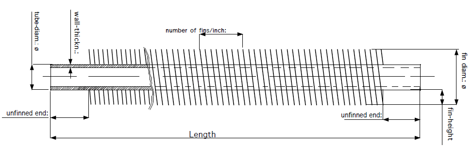
ASTM A179 Fin Tubes is formed by passing a tube through a set of rollers that form the fins from the parent material of the tube by making it flow in the desired way.
ASTM A179 Fin Tubes is formed by passing a tube through a set of rollers that form the fins from the parent material of the tube by making it flow in the desired way.

High finned tubes are also called extruded tubes. The finning is achieved by extruding the fin from the tube.

This method of construction is very different from cutting grooves onto the tube as is often done by people who are on the lookout for a shortcut or who don’t know any better.

Base tube diameters
| Inch | mm |
| 5/8″ 3/4″ 1″ 1 1/4″ 1 1/2″ 1 3/4″ 2″ |
15,88 19,05 25,40 31,75 31,75 44,40 50,80 |
Fin-heights
| Inch | mm |
| 3/8″ 1/2″ 5/8″ |
9,55 12,70 15,8 |
number of fins
| fins per inch | fins per meter |
| 7 8 9 10 11 12 |
275 315 354 394 433 473 |
Transferring heat from a hot fluid into a colder fluid through a tube wall is the reason many of us use finned tubes. But you may ask, what is the major advantage of using a finned tube? Why can’t you just use a regular tube to make this transfer? Well you can but the rate will be much slower.
By not using a finned tube the outside surface area is not significantly greater than the inside surface area. Because of that, the fluid with the lowest heat transfer coefficient will dictate the overall heat transfer rate. When the heat transfer coefficient of the fluid inside the tube is several times larger than that of the fluid outside the tube the overall heat transfer rate can be greatly improved by increasing the outside surface area of the tube.
Finned tubes increase outside the surface area. By having a finned tube in place, it increases the overall heat transfer rate. This then decreases the total number of tubes required for a given application which then also reduces overall equipment size and can in the long-run decrease the cost of the project. In many application cases, one finned tube replaces six or more bare tubes at less than 1/3 the cost and 1/4 the volume.
For applications that involve the transfer of heat from a hot fluid to a colder fluid through a tube wall, fin tubes are used. Usually, for an air heat exchanger, where one of the fluids is air or some other gas, the air side heat transfer coefficient will be much lower, so additional heat transfer surface area or a fin tube exchanger is very useful. The overall pattern flow of a finned tube exchanger is often crossflow, however, it can also be parallel flow or counterflow.
Fins are used to increase the effective surface area of heat exchanger tubing. Furthermore, finned tubes are used when the heat transfer coefficient on the outside of the tubes is appreciably lower than that on the inside. In other words, heat transferred from liquid to gas, vapor to gas, such as steam to air heat exchanger, and thermic fluid to air heat exchanger.
The rate at which such heat transfer can occur depends on three factors – [1] the temperature difference between the two fluids; [2] the heat transfer coefficient between each of the fluids and the tube wall; and [3] the surface area to which each fluid is exposed.
Increase Heat Transfer Rate:
A finned tube exchanger typically has tubes with fins attached to the outside. Usually, there will be some liquid flowing through the inside of the tubes and air or some other gas flowing outside the tubes, where the additional heat transfer surface area due to the finned tube increases the heat transfer rate. In a crossflow fin tube exchanger, the fins will typically be radial fins and they’ll either be circular or square in shape.
Improve Heat Transfer Coefficient:
By not using a finned tube, the outside surface area is not significantly greater than the inside surface area. Because of this, the fluid with the lowest heat transfer coefficient will dictate the overall heat transfer rate. When the heat transfer coefficient of the fluid inside the tube is several times larger than that of the fluid outside the tube, the overall heat transfer rate can be greatly improved by increasing the outside surface area of the tube.
Increase Outside Surface Area:
By having a finned tube in place, it increases the overall heat transfer rate. Finned tubes increase the outside surface area. This decreases the total number of tubes required for a given application which then also reduces overall equipment size and can in the long-run decrease the cost of the project.
Finned tube heat exchangers are used in a variety of applications, and more so as industrial heat exchangers. An air heat exchanger like the evaporator coil in an air conditioning unit is typically a fin tube exchanger. Another common fin tube air heat exchanger is the car radiator. The purpose of the car radiator is to cool the hot water in the tubes with the air passing through the crossflow. On the contrary, the air conditioner evaporator coil has the purpose of cooling the air passing through it. The finned tubes that are manufactured at Kainon Boilers, use high grade carbon steel, stainless steel, copper, brass, and aluminum. Our finned tube exchangers are designed to meet the specific duty condition, temperature and pressure of the fluids.
| Type | Description | Base tube | Fin specification (mm) | ||
|---|---|---|---|---|---|
| O.D. (mm) | Fin pitch | Fin height | Fin thick | ||
| Embedded | G-type fin tueb | 16-63 | 2.1-5 | <17 | ~0.4 |
| Extruded | Single metal combined metal | 8-51 | 1.6-10 | <17 | 0.2-0.4 |
| Low fin tube t-type fin tube | 10-38 | 0.6-2 | <1.6 | ~0.3 | |
| Bamboo tube corrugated tube | 16-51 | 8-30 | <2.5 | / | |
| Wound | l/kl/ll type fin tube | 16-63 | 2.1-5 | <17 | ~0.4 |
| String | String fin tube | 25-38 | 2.1-3.5 | <20 | 0.2-0.5 |
| U-type | U-type tube | 16-38 | / | / | / |
| Welding | HF-welding fin tube | 16-219 | 3-25 | 5-30 | 0.8-3 |
| H/HH type fin tube | 25-63 | 8-30 | <200 | 1.5-3.5 | |
| Studed fin tube | 25-219 | 8-30 | 5-35 | φ5-20 | |
According to user needs, we can produce all kinds of steel strip winding finned tube and steel aluminum composite finned tube.
For Aluminum L-Foot finned tubes, the fin material is aluminum, either 1100-0. The tube material is generally carbon steel, stainless steel, or brass; however the tube can be of any material.
For Welded Helical Solid and Welded Helical Serrated finned tubes, the fin and tube materials can be any combination that can be welded together using HIGH FREQUENCY WELDING process.
The materials chosen for a given application are a function of service temperature, corrosive environment, and/or erosive environment. Common tube materials used for our welded product lines include: carbon steel, carbon moly, chrome moly, stainless steel, Inconel, and Incoloy. Common fin materials include: carbon steel; stainless steels of types 304, 310, 316, 321, 409, and 410; Nickel 200, and Inconel.
 Carbon steel fins are available on carbon, stainless steel, or copper tube. Please call for a specific size if not listed
We offer you a broad portfolio of materials and can expand our offering at any time to meet your specific needs regarding thermal conductivity, mechanical properties, or corrosion resistance.
Specific classification of finned tubes, there are lot of types of finned tubes, meanwhile also lot of new species comes up.
And so on.
The material certificate including all the tests can be provided, and also with EN10204 3.1standard.
Fin tubes are used in applications involving the transfer of heat from a hot fluid to a colder fluid through a tube wall. Furthermore, finned tubes are used when the heat transfer coefficient on the outside of the tubes is appreciably lower than that on the inside.
The rate at which such heat transfer can occur depends on three factors:
When the heat transfer coefficient of the fluid inside the tube is several times larger than that of fluid outside the tube (for example steam inside and oil outside), the overall heat transfer rate can be greatly improved by increasing the outside surface of the tube. In mathematical terms, the product of heat transfer coefficient for the outside fluid multiplied by the outside surface area is made to more closely match the product of the inside fluid heat transfer coefficient multiplied by the inside surface area.
So the whole concept of finned tubes is to increase the outside surface area of the tube. As an example, a finned tube configuration of 2” (nominal, 2.375” actual) pipe with a ¾” high welded helical solid fin of 12 gauge thickness with 6 fins per inch has an outside surface area of 8.23 sq. ft. per linear foot; whereas the same bare pipe has an outside surface area of only .62 sq. ft. per linear foot. That is a 13X increase in outside surface area. See Design Information for extensive tables of surface areas and fin weights.
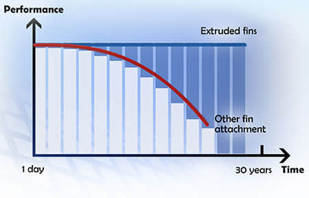 Extruded fins performance charts
By increasing the outside surface area of the tube, the overall heat transfer rate is increased, thereby reducing the total number of tubes required for a given application.
This reduces the overall equipment size and the cost of the project. In many cases, one finned tube replaces six or more bare tubes at less than 1/3 the cost and ¼ the volume.
In other words, the heat transferred from liquid to gas, vapor to gas, such as steam to air heat ex-changer, and thermic fluid to air heat ex changer. According to different materials and fabrication process, there are several kinds of fin tubes, such as extruded fin tube, crimped spiral fin tube, G type embedded fin tube, L/KL/LL Foot Fin Tube, etc.
Used as heat transfer element, fin tubes are usually working under high temperature with flue gas. For example, the condition for boiler heat ex-changer fin tube is very bad, high temperature, high pressure in corrosive atmosphere. In this case, the finned tubes should have a high performances.
They are widely used in food processing, timber drying, dyeing and printing industry, paper mill plant, pipeline transport, gas recovery, gas pre-heater, textile industry, power transfer, etc.
Generally, tubes equipped with surface enhancing devices, such as fins or grooves, are used where heat exchange is required between two fluids whose ability to transmit calories is very far apart. For a water / air exchange, for example, the local exchange coefficient on the water side is much higher than that on the air side. Thus, fins are added to the surface in contact with air in order to increase the density of the heat flux between the two fluids.
Being the only interface between the hot and cold source, the extruded finned tube is at the heart of heat transfer. Its quality plays a key role in the ability of an exchanger to efficiently transfer thermal energy between the two fluids. More precisely, the way in which the fin is secured to the tube affects the efficiency of the exchanger in the short, medium and long term.
Indeed, studies have shown that the main cause of the loss of efficiency of an exchanger is due to a loss of quality of the fin attachment to the tube. Indeed, after a few thermal cycle, a gap between the fins and the tubes occurs due to thermal expansion and vibrations.
According to the heat exchange application and operation, there are various materials.
The common ones are Aluminum, Alloy, Copper, Brass, Nickel, Titanium, Stainless Steel, Carbon Steel, etc, among which the aluminum and alloy are mostly used.
The basic performance for fin tube heat exchange should be with good solder ability and form ability, higher mechanical strength, good corrosion resistance and thermal conductivity. In spite of these, aluminum and alloy are also featured in extension and higher tensile strength increases under lower temperature. Around all world, especially for low temperature and compact heat exchange, they are widely applied.
Let’s see the feature of aluminum
1. Low Density
By alloying and heat treatment, it can reach the structural of construction steel. Suitable for various transportation, especially for small vehicle, reducing weight and consumption.
2. Good Corrosion Resistance
When under harsh conditions, the materials oxide from aluminum is non-toxic. With aluminum heat exchange, no worries that air or liquid inside will be destructed by oxide after long time.
3. Good Thermal Conductivity
Especially suitable for radiating fin, heat transfer evaporator and condenser.
4. High Yielding and resistance to die cutting.
It is easy for processing and forming.
As a professional finned tube manufacturer, our leading product is aluminum finned tube. Should you have any interest, please contact us for more.
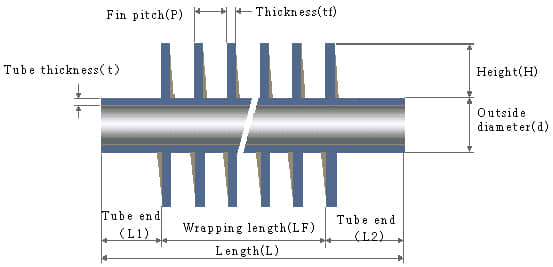 Fin tube ration affected by fin height, fin thickness and fin pitch
When the fins are root-grounded on the base bare tube, in the case of heat from inside to outside, the heat will be transferred from fin root along fin height. It is also continuously transmitted to the surrounding fluid by convective heat transfer. As a result, the fin temperature gradually decreases along the altitude. This also illustrates that difference between fin temperature and ambient fluid temperature is reducing gradually and the heat change per unit is shrinking. Therefore, the effect of fin surface area on enhanced heat transfer is decreasing. The higher the fin, the contribution of the increased area to heat exchange is smaller.
Generally speaking, as for the high frequency welded fin tube applied in engineering project, when fin height is 15mm, the fin efficiency is about 0.8; when fin height is 20mm, the fin efficiency is decreased to 0.7. Based on this, 15mm is the best height. If fins height above 20mm, the fin efficiency will be very bad, so generally not adopted. However, for the aluminum fin on air cooler, height at 22-25mm are always adopted due to much better heat conductivity coefficient of aluminum than carbon steel.
How will fin pitch affect fin ratio?
Usually smaller pitch can effectively increase fin ratio. While considering the flow gas property and ash deposit , we should pay attention to following factors.
A. Serious heavy ash deposit
Such as electric furnace and converter in steel works and exhaust of industrial cellar furnace, the ash content is heavy. If fin tubes are used for heat exchange, larger fin pitch will be suggested. For example, if pitch above 10mm, it is necessary to add a air discharge and choose an air blower.
B. Occasion with small ash deposit but should also be cared.
Take exhaust on plant boiler and industrial boiler as example, 8mm fin pitch is suitable, but should be designed with self-blowing ability.
C. Occasion with no dust or light dust.
Such as exhaust on burning natural gas equipment or air cooler, fin pitch at 4-6mm is OK. For aluminum air cooler, 3mm as fin pitch is also chosen.
The choice on fin thickness depends on corrosion and abrasion of fluid gas. Usually thicker fin is used on site with heavy corrosion.
Aluminum extruded fin tube is widely applied in barley malt, paper mill, timber drying, tobacco, food processing, coal mining, petrochemical, chemical fiber, construction materials, printing and dyeing, as more than 30 industries.
Meantime, they are also complementing for equipment such as air conditioner, drying oven, drying room, air coolers and so on.
Extruded aluminum fin tube is rolled as an integrity with no thermal contact resistance, high intensity, featured in thermal shock and mechanical shock resistance. Heat exchangers assembled with this kind of fin tube (extruded fin type) is much better than the one equipped with string fin tubes or hectically wound fin tubes (L/LL/KL type fin).
Extruded Aluminum Finned Tubes, also known as “Integral Finned Tubes”. Integral finned tubes are manufactured by rolling process on tubes. During finning operation, the inside diameter of the tubes is reduced and helical fins are rolled on the tube wall. The tubes material can be Copper Alloy, Brass Alloys, Copper Nickel Alloy, Titanium Alloy, Stainless Steel, Duplex Stainless Steel etc. The pressure required to extrude fins from the aluminum sleeve creates an excellent “pressure bond” between the two materials.
Copper and aluminum com-posited fin tubes are rolled from a muff copper tube, advantaged in tight link, small thermal resistance, good heat transfer efficiency, small flow loss and strong corrosion resistance. When working in long time under heating and cooling conditions, they are durable and not easy to deform.
The integral extruded fin tubes is smooth on surface and easy to clean. When wet cooling in heating and air conditioning project, it is easy to remove the condensation water on the outer surface of the fin, and it is not easy to dust and scale in the heating and other heat exchange.
The fin strip is wound into a machined groove and securely locked into place by back filling with the base tube.
G fin tube consists of aluminum fin strip that is mechanically embedded into the wall of the tube. The embedding process is controlled by tooling that first plows a groove into the tubes outside diameter, then guides the base of the fin into the groove and finally locks the fin in place by rolling the groove closed on the base of the fin. This ensures that maximum heat transfer is maintained at high tube metal temperature 400°C.
The aluminum fin strip or the copper fin strip is folded into an L shape and spirally wound tightly under the action of tension on the outer surface of the base tube. Tension in the fin strip is wrapped around the tube serves to make the fin foot forcefully on the tube, thus hold the fin firmly in place.
An L-shaped foot, 1/16″ wide, is first formed on one side of the fin strip (hence the name L-Foot). The strip is then wound tightly around the tube, with the foot bearing on the tube outer surface. A typical fin spacing is 10 fins per inch of tube length — this can be varied. Tension in the fin strip as it is wrapped around the tube serves to seat the fin foot forcefully on the tube, and to hold the fin firmly in place.
Extruded aluminum finned tubes, also known as “integral finned tubes”. Integral finned tubes are manufactured by rolling process on tubes. During finning operation, the inside diameter of the tubes is reduced and helical fins are rolled on the tube wall.
Integral Low Finned Tubes
Integral Medium High Finned Tubes
Low Finned U Bend Tubes
Low finned tubes with internal rib
Low Finned Tubes Coils
High Finned Tubes
Corrugated Tubes
Extruded Aluminum Finned Tubes Characteristics
Extruded Aluminum Finned Tubes Benefits
Extruded Aluminum Finned Tubes Quality Assurance
Extruded Aluminum Finned Tubes Applications
It is fabricated with a batch of single fins that were processed by the punch press and then manually or mechanically, with a certain distance (wingspan) on the base tube.
This is the earliest fin tube fabrication with low cost and simple production process/ technology, easy to maintain. Divides into manual set and mechanical set. Manual set uses a tool that relies on the power of man to press the fins one by one. This method is limited by the pressure of the fin, so it is easy to get loose. The machine – set fin is carried on the wing piece machine. Due to the mechanical impact or liquid pressure, the pressure of the fin is high, so it can be used in a larger volume. The bonding strength between fin and tube is high and not easy to loosen. Mechanical transmission has high productivity, but the noise is large, the safety is poor, and the working conditions of the workers are not good. Although the hydraulic transmission does not have the above problem, but the equipment price is more expensive, the technical requirement to use maintenance personnel is higher, its productivity is also lower.
Currently HF Fin Tube is one of the most widely used helical fin tubes, you can see it as waste heat recovery in power, metallurgy, concrete, oil and gas, petrochemical, etc. When winding the steel strip around steel tube, the use of high frequency current skin effect and proximity effect on steel strip and steel pipe surface heating, until the plastic state or melt, the coil steel belt must be under pressure to complete welding. Comparing with embedded type and spot welding spiral crimped type, it is more advanced either on fin tube quality or production efficiency or automation degree.
The extruded fin is formed from an outer aluminum tube with a large wall thickness (muff), which is aligned over an inner base tube. The two tubes are pushed through three arbors with rotating discs that literally squeeze or extrude the aluminum fins up and out of the muff material in a spiral shape in one operation. Comparing with welding fin tube, dr extruded fin has higher production efficiency with low cost on material and high heat transfer. At present, it divides into copper or aluminum single metal fin tube and bi-metal composited fin tube.
Fin tube manufacturers produce a wide range of fin tubes. They are used in heat exchangers (air, water and chemically cooled) for various industries such as petroleum, petrochemical, steel, power generation and many more.
Corrosion protection processes are performed during fin tube manufacturing and the material used is corrosion resistant. Some fin tube types are:
| Type | Photo | Descriptions | Properties |
|---|---|---|---|
| "KL" fin tubes | 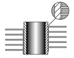 | After application the fin foot is knurled into the corresponding knurling on the base tube thereby enhancing the bond between the fin and tube resulting in improved heat transfer characteristics. Max. operating. temp. 260ºC | Max working temperature – 260 °C (500 °F) Atmospheric corrosion resistance – acceptable Mechanical resistance – acceptable Fin material – aluminum, copper |
| "G" fin tubes | 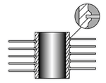 | Fin strip is wound & embedded on a groove and securely locked by closing the groove with the base tube metal. This ensures maximum heat transfer at high temperatures. Max. operating temp. 450ºC | Max working temperature – 400 °C (752 °F) Atmospheric corrosion resistance – poor Mechanical resistance – acceptable Fin material – aluminum, copper, carbon steel |
| "LL" fin tubes | 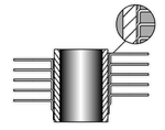 | Manufactured in the same way as the ‘L’ fin type except that the fin foot is overlapped to completely enclose the base tube thereby giving excellent corrosion resistance. This type of tube is often used as an alternative to the more expensive extruded type fin in corrosive environments. Max. operating. temp. 180ºC | Max working temperature – 180 °C (356 °F) Atmospheric corrosion resistance – acceptable Mechanical resistance – poor Fin material – aluminum, copper |
| “L” fin tubes | 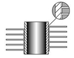 | The strip material is subjected to controlled deformation under tension giving the optimum contact pressure of the foot of the fin onto the base tube thus maximizing the heat transfer properties. The foot of the fin considerably enhances the corrosion protection of the base tube. Max. operating. temp. 150ºC | Max working temperature – 150 °C (302 °F) Atmospheric corrosion resistance – acceptable Mechanical resistance – poor Fin material – aluminum, copper |
| Extruded fin tubes | 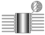 | This fin type is formed from a bi-metallic tube consisting of an aluminium outer tube and an inner tube of almost any material. The fin is formed by rolling material from the outside of the exterior tube to give an integral fin with excellent heat transfer properties and longevity. Extruded fin offers excellent corrosion protection of the base tube. Max. operating. temp. 280ºC. | Max working temperature – 285 °C (545 °F) Atmospheric corrosion resistance – excellent Mechanical resistance – excellent Fin material – aluminum |
We are a pretty proactive bunch. So, while we do charge a small fee per design to cover our costs, we absorb these costs when it is for a regular customer or where we are working jointly on a project. We also refund the fees in case it is followed by an order.
Can you assist with the design for my application?
Absolutely, we can.
Applied Fin Tube
Applied Fin Tube is made with strip wrapped under tension around the base of the tube. Fins are welded to the base tube at the strip ends.
Why do Pin fin tubes weigh less than L type fin tubes?
Pin Fin tubes are made from wire. Being cylindrical, wire has a larger area per unit of weight than the strip used in L type fin tubes. Also, due to the looped nature of the wire, less material is put on the tube than in the case of L fins. Consequently, the surface area of fins per meter of tubes is also less. However due to the superior turbulence created by the looped wire the actual heat transfer per meter of tube is significantly higher than in the case of L Type Fin Tubes. All of this together contributes to the weight differential between wire wound fin tubes and L Type Fin Tubes. In the case of similar metals, it is weighing half and in the case of Aluminium L fin vs. Steel wire fin they weigh about the same. The higher performance S5 pin fin tubes have an airside heat transfer performance per meter of tube that is 250% of the L type fin tubes.
Can Sunny Steel supply my fin tubes?
Yes. A lot of our customer choose to supply their own pipes or tubes, however, a lot of customers ask us to supply them and we are happy to accommodate! We stock various sizes and if we don’t have what you need we can bring it in from one of our many suppliers. If you would like us to include the pipe or tube material in your order, please indicate that when you request a QUOTE.
High Frequency Resistance Welding
A continuous helical fin is attached to the base tube by high frequency electric resistance welding in order to give an efficient and thermally reliable bond. Fins can be either solid or serrated (segmented). The weld produced in this process is a true forge, blacksmith weld. This type of weld is comprised of a fusion between two portions of parent metal without the introduction of a filler material. The weld is simply produced by heating the interfaces to be joined to a plastic state and applying pressure.
Used in boilers, furnaces and fired heaters for efficient heat recovery.
Uses of finned tubes
The main uses for high frequency welded finned tubes are in the heat recovery associated with boilers for power generation and in furnace applications for the petrochemical industry.
Tube bending:
Our finning machines are equipped with online single or duplex cold bending equipment that can manipulate both ends of tubes in a single operation, thus ensuring exact alignment of the ends.
Do we stock fin tubes?
We do not. Our market lends itself to customer designed products, each special in itself. The number of combinations of diameter, overall length, materials and fin specs are too vast. Sunny Steel builds each finned product to each customers needs.
What are finned tubes used for?
Finned tubes are the main components of heat exchangers. They are a series of tubes where fins have been added on the outside to increase the contact area with the outside fluid, to exchange heat and between the fluid inside the tube and the fluid outside the tube. Finned tubes are elongated aluminium cladded carbon steel flat tubes with brazed aluminium fins.
The rate at which such heat transfer can occur depends on three factors:
(1) the temperature difference between the two fluids;
(2) the heat transfer coefficient between each of the fluids and the tube wall; and
(3) the surface area to which each fluid is exposed. In the case of a bare (unfinned) tubes, where the outside surface area is not significantly greater than the inside surface area, the fluid with the lowest heat transfer coefficient will dictate the overall heat transfer rate. When the heat transfer coefficient of the fluid inside the tube is several times larger than that of fluid outside the tube (for example steam inside and oil outside), the overall heat transfer rate can be greatly improved by increasing the outside surface of the tube. In mathematical terms, the product of heat transfer coefficient for the outside fluid multiplied by the outside surface area is made to more closely match the product of the inside fluid heat transfer coefficient multiplied by the inside surface area.
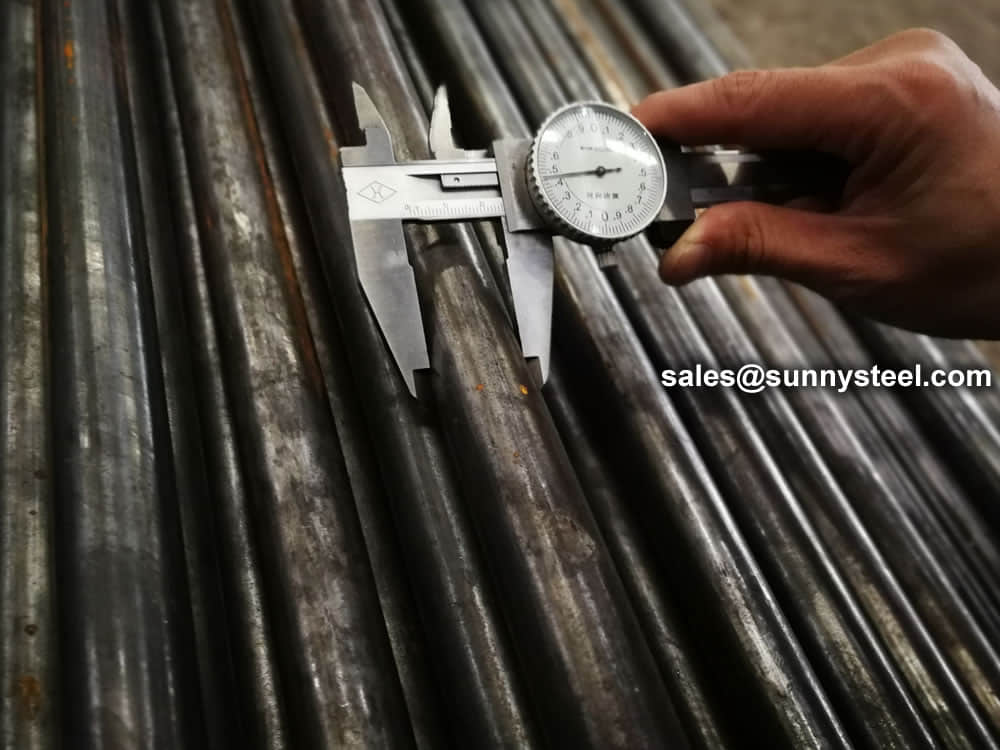
The first actual inspection work on the fin tube heat exchanger is the raw materials inspection. Based on the ASME Code, providing material test reports for fin tube heat exchanger plates is mandatory. For other components, the marking inspection will be enough.
Inspection steel coil
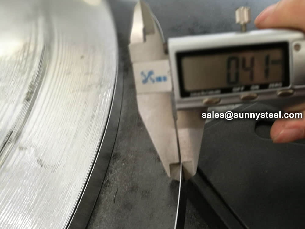
Inspection steel coil
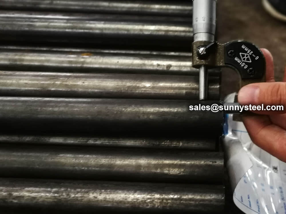
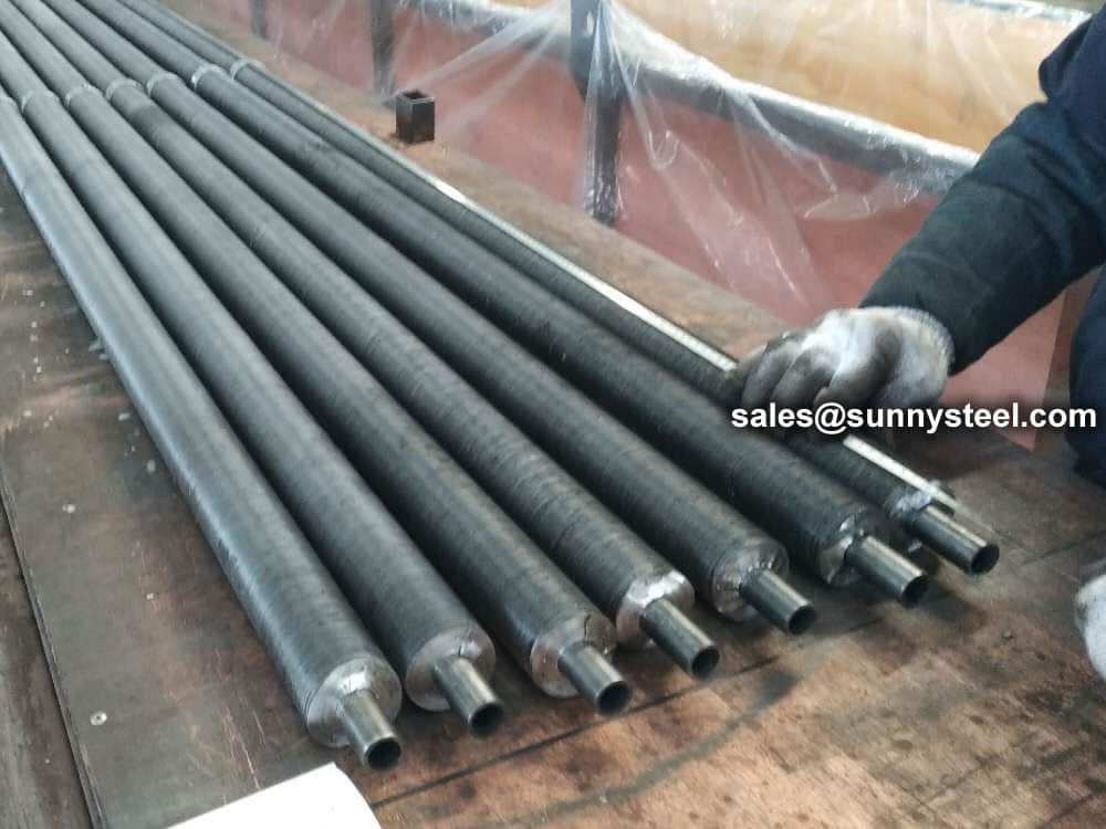
Inspection raw tubes
Inspection raw tubes
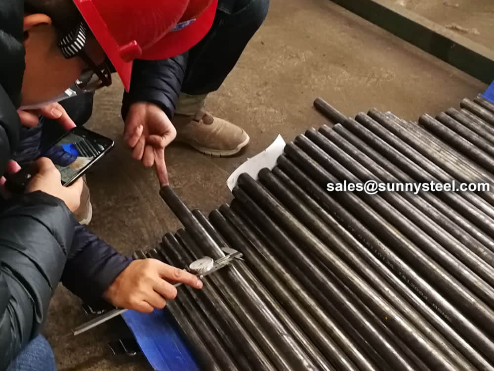
Inspection raw tubes
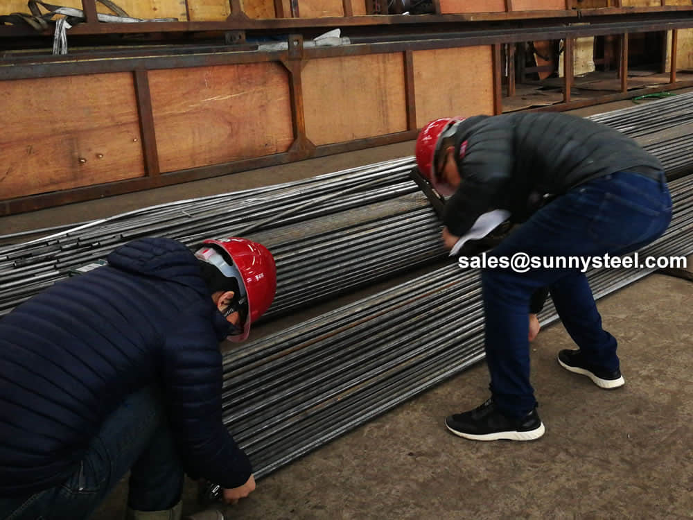
Inspection raw tubes
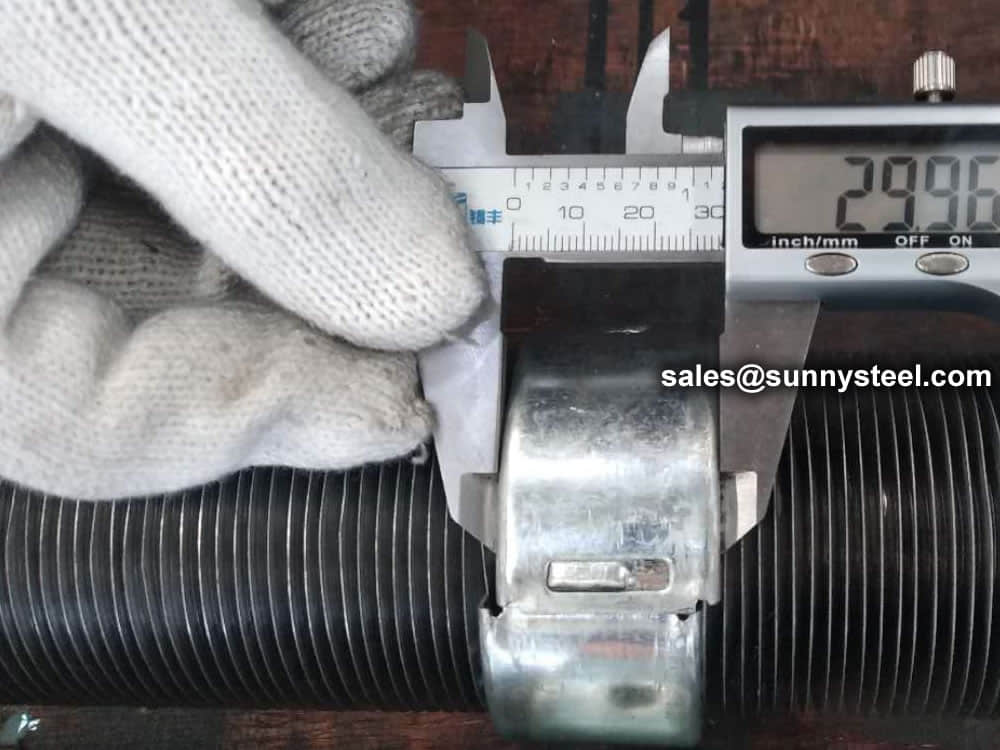
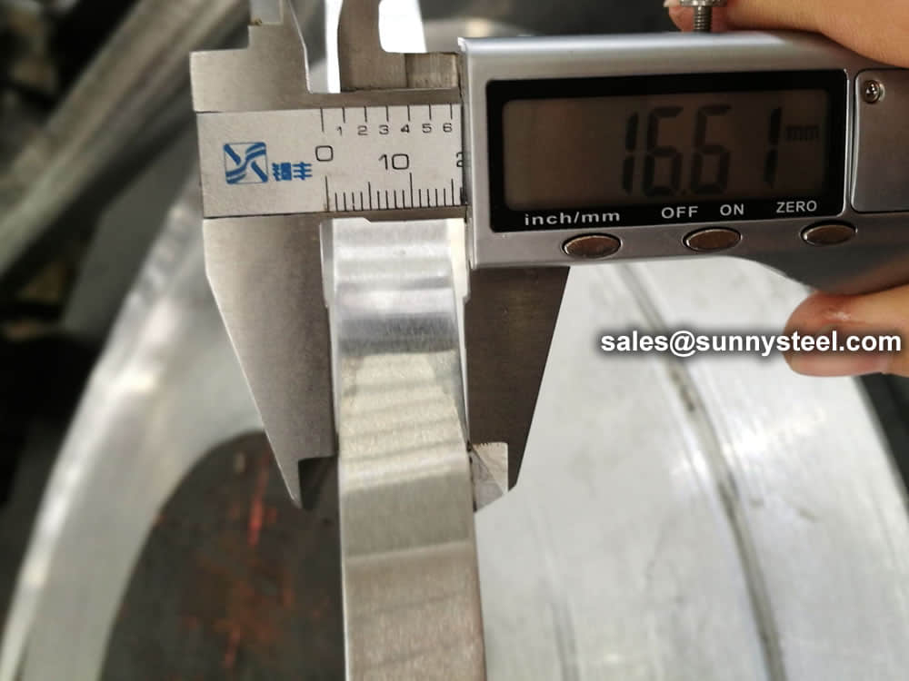
Inspection ring
Inspection ring
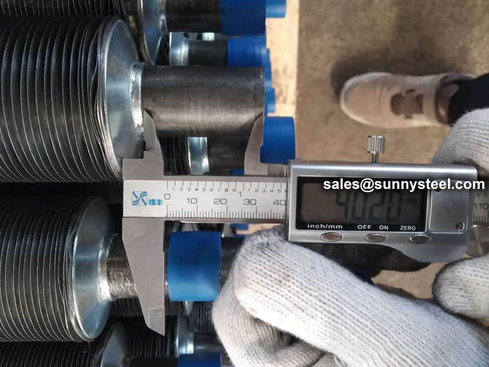
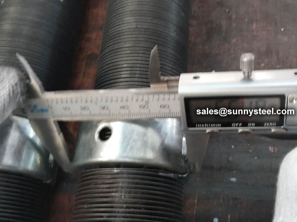
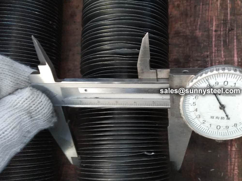
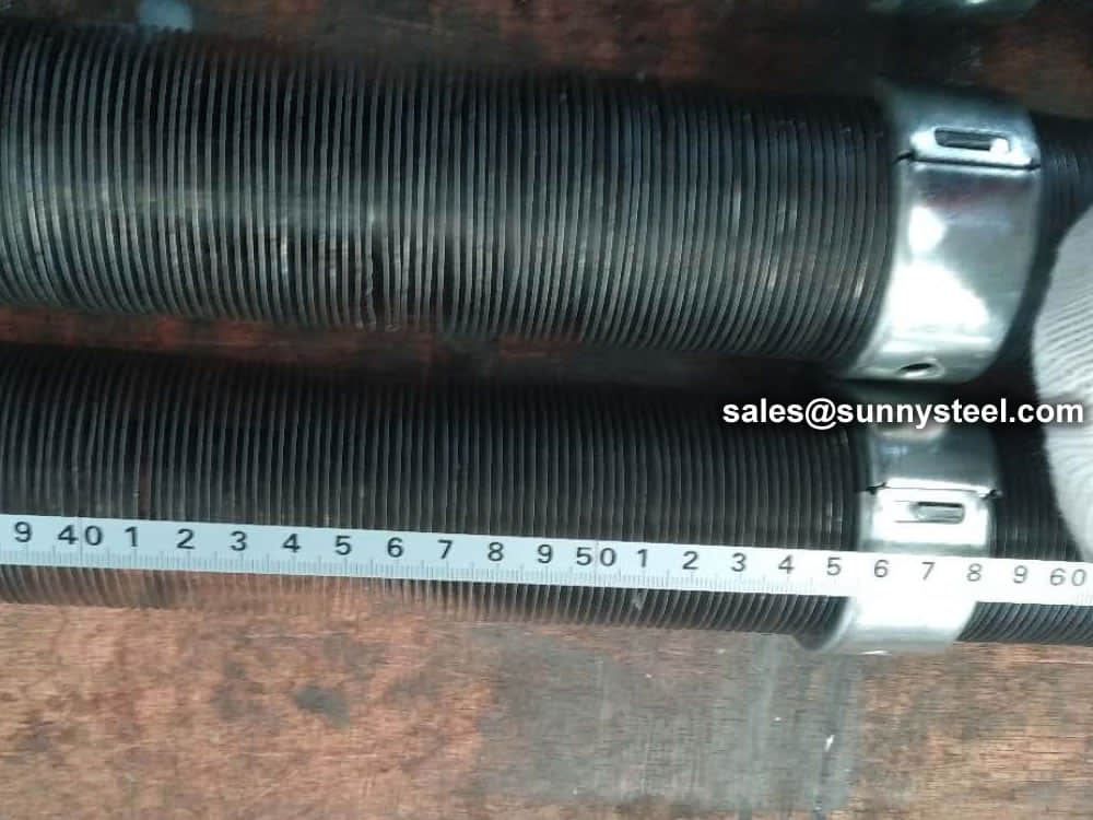
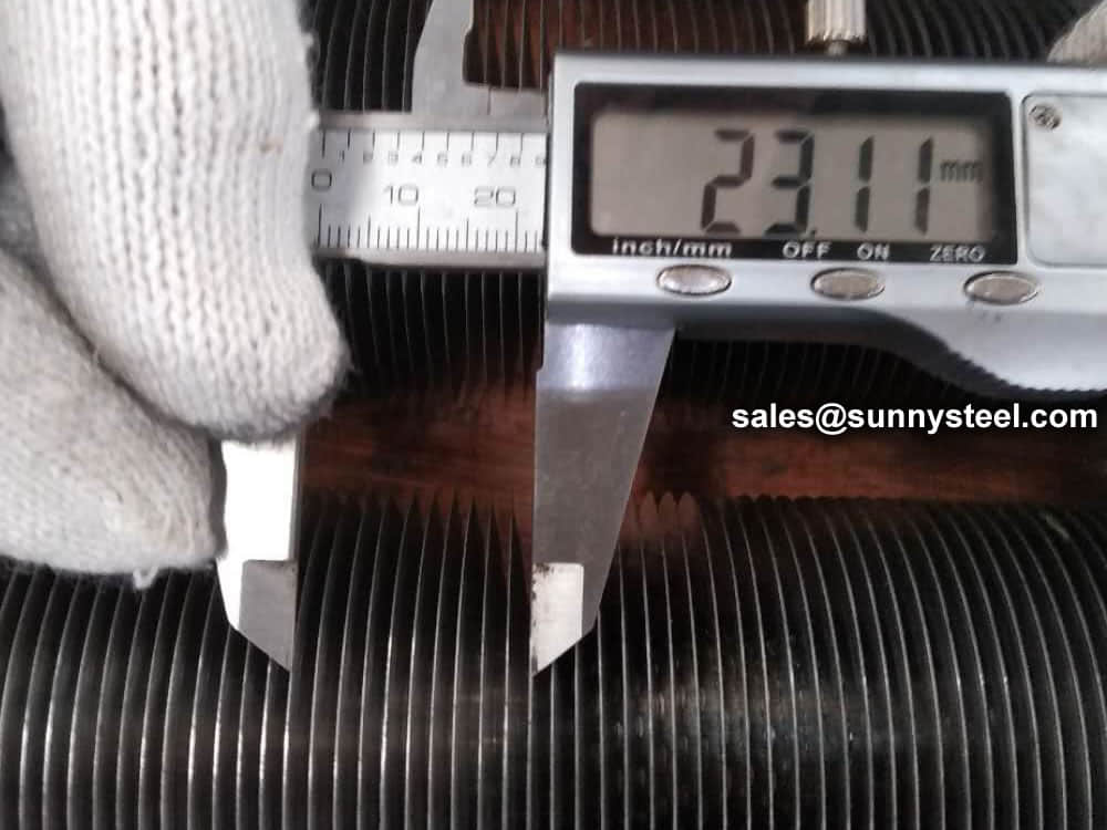
Inspection fin tube size
The Finned Tube is exposed to the outside to prevent rainwater from falling, try to keep it dry, and it should not be too close to the ground to prevent the irrigation in the greenhouse from corroding the finned tube. After the maintenance of the finned tube, the service life of the finned tube will be greatly increased.
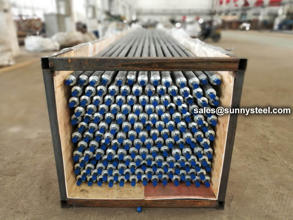
Packing in wooden cases
Packing in wooden cases
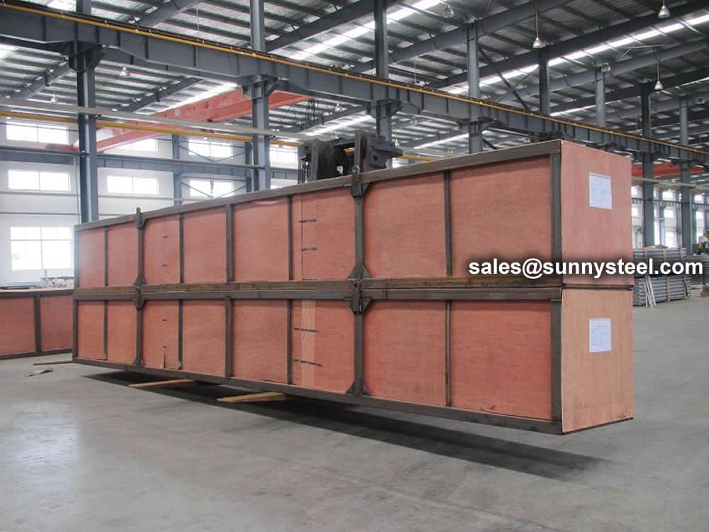
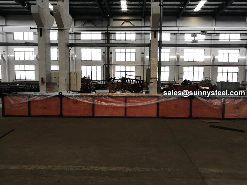
Well packing in wooden cases
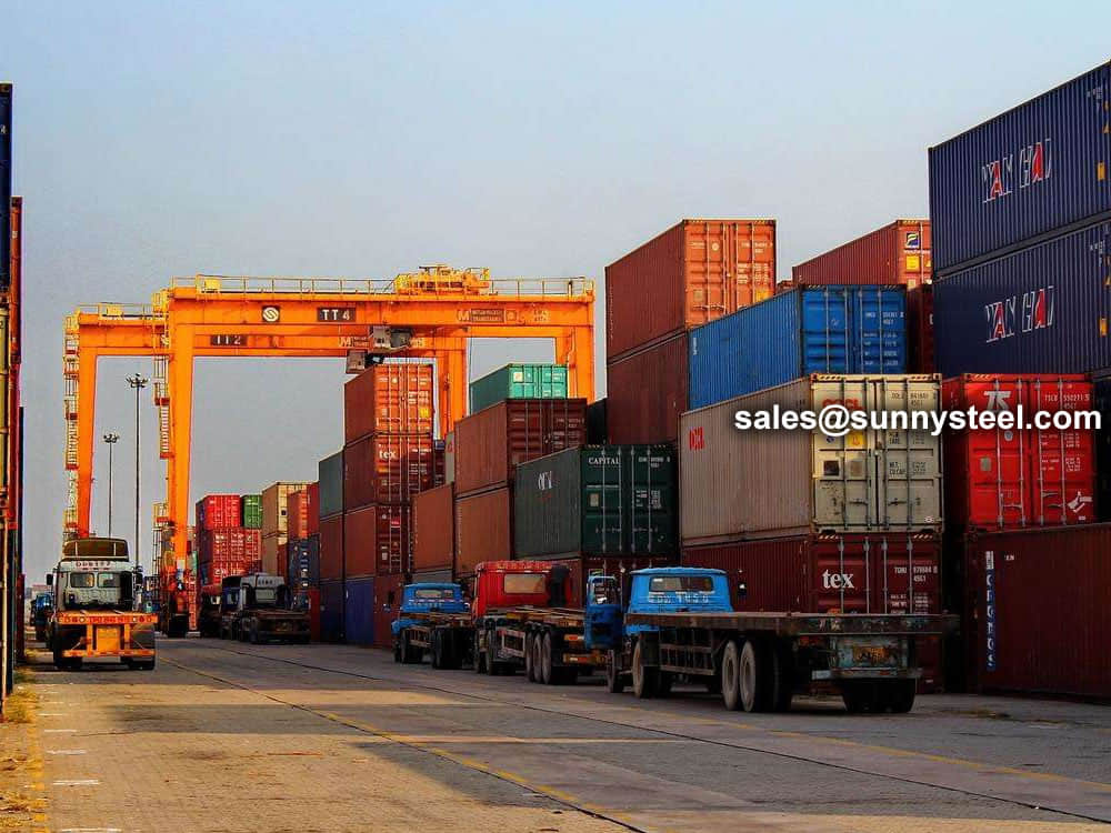
Delivery to sea port by vessel
Need to inquire about our products? Fill out the form below and our staff will be in touch!
Q: How long is your delivery time?
A: The delivery time of customized products is generally 25 35 days, and non customized products are generally shipped within 24 hours after payment.
Q: Do you provide samples? Is it free?
A: If the value of the sample is low, we will provide it for free, but the freight needs to be paid by the customer. But for some high value samples, we need to charge a fee.
Q: What are your payment terms?
A: T/T 30% as the deposit,The balance payment is paid in full before shipment
Q: What is the packaging and transportation form?
A: Non steaming wooden box and iron frame packaging. Special packaging is available according to customer needs. The transportation is mainly by sea.
Q: What is your minimum order quantity?
A: There is no minimum order quantity requirement. Customized products are tailor made according to the drawings provided by the customer.


