Our team is highly trained and experienced in servicing and producing all types of steel supplies. Need help or have a question?
sales@abrasionresistantpipe.com
Tel.: +8621-3378-0199
Our team is highly trained and experienced in servicing and producing all types of steel supplies. Need help or have a question?
sales@abrasionresistantpipe.com
Tel.: +8621-3378-0199

ASTM A234 WP11 Fittings can effortlessly be bent and welded. ASME SA 234 wp11 that shape significant connections between numerous pipes of different sizes. ANSI B16.9 Elbow A234 WP11 is the free machining version of this grade, accessible in a bar shape for utilizing in automatic screw machines.
ASTM A420 WPL6 Elbow after complete quality and performance measure inspection. These are widely appreciated for excellent quality, corrosion abrasion and high tensile strength with long life service.
Materials shall consist of forgings, bars, plates, seamless or fusion welded tubular products with filler metal added, and shall be produced by open-hearth, basic-oxygen, or electric-furnace process. Forging or forming operations shall be performed by one or a combination of two or more of the following procedures: hammering, pressing, piercing, extruding, upsetting, working, bending, fusion-welding, or machining. All welding shall be completed prior to the austenitizing heat treatment, which shall be executed in the normalized, normalized and tempered, annealed, or quenched and tempered conditions. Steel specimens shall conform to required values of chemical composition, tensile strength, yield strength, elongation, wall thickness, and Charpy V-notch impact value. All fusion-welded butt joints shall undergo radiographic examination, while hydrostatic testing of fittings is not required in this specification. Repair welding shall be permissible for parts made to dimensional standards.
| Elements | WPL6, % | WPL9, % | WPL3, % | WPL8, % |
|---|---|---|---|---|
| Carbon [C] | ≤0.30 | ≤0.20 | ≤0.20 | ≤0.13 |
| Manganese [Mn] | 0.50-1.35 | 0.40-1.06 | 0.31-0.64 | ≤0.90 |
| Phosphorus [P] | ≤0.035 | ≤0.030 | ≤0.05 | ≤0.030 |
| Sulfur [S] | ≤0.040 | ≤0.030 | ≤0.05 | ≤0.030 |
| Silicon [Si] | 0.15-0.40 | … | 0.13-0.37 | 0.13-0.37 |
| Nickel [Ni] | ≤0.40 | 1.60-2.24 | 3.2-3.8 | 8.4-9.6 |
| Chromium [Cr] | ≤0.30 | ... | ... | ... |
| Molybdenum [Mo] | ≤0.12 | ... | ... | ... |
| Copper [Cu] | ≤0.40 | 0.75-1.25 | … | … |
| Columbium [Cb] | ≤0.02 | ... | ... | ... |
| Vanadium[V] | ≤0.08 | ... | ... | ... |
| ASTM A420/ A420M | Tensile Strength, min. | Yield Strength, min. | Elongation %, min | |||
|---|---|---|---|---|---|---|
| Grade | ksi | MPa | ksi | MPa | Longitudinal | Transverse |
| WPL6 | 65-95 | 415-655 | 35 | 240 | 22 | 12 |
| WPL9 | 63-88 | 435-610 | 46 | 315 | 20 | … |
| WPL3 | 65-90 | 450-620 | 35 | 240 | 22 | 14 |
| WPL8 | 100-125 | 690-865 | 75 | 515 | 16 | … |
| Charpy Impact Requirements for WPL6, WPL9, and WPL3 | ||||
|---|---|---|---|---|
| Size of Specimen | A* | B* | ||
| mm | ft·lbf | J | ft·lbf | J |
| 10 by 10.0 | 13 | 17.6 | 10 | 13.6 |
| 10 by 7.5 | 10 | 13.6 | 8 | 10.8 |
| 10 by 5.0 | 7 | 9.5 | 5 | 7 |
| 10 by 2.5 | 4 | 5.4 | 3 | 4.1 |
Varieties classification
Carbon steel elbow is first divided into its radius of curvature, which can be divided into long radius elbows and short radius elbows. The long-radius elbow refers to its radius of curvature equal to 1.5 times the outer diameter of the tube, ie R = 1.5D. A short-radius elbow means that its radius of curvature is equal to the outer diameter of the tube, ie R = 1.0D. (D is the diameter of the elbow, and R is the radius of curvature. D can also be expressed in terms of folds.) If there are 17 levels depending on the pressure rating, the same standards as in the U.S. tube are: Sch5s, Sch10s, Sch10 , Sch20, Sch30, Sch40s, STD, Sch40, Sch60, Sch80s, XS; Sch80, Sch100, Sch120, Sch140, Sch160, XXS, the most commonly used are STD and XS. According to the angle of the elbow, there are 45° elbows, 90° elbows and 180° elbows.
What is the radius of curvature?
Radius of curvature is the curvature of a curve. The curvature of a plane curve is defined as the rotation rate of the tangent angle of a point on the curve to the length of the arc. It is defined by differentiation and it shows the degree of the curve deviating from the line. The reciprocal of curvature is the radius of curvature. The radius of curvature is mainly used to describe the extent of curvature variation of a point on a curve.
Technical requirements for the long radius elbow
It is required that the radius of curvature should be controlled. For example, if the radius is 1.5D, then the radius of curvature must be within the required tolerance range. Because most of these pipe fittings are used for welding, in order to improve the quality of welding, the end will be turned into the groove and it will keep the certain angle and edge. This requirement is quite strict, and the thickness of the edge, the angle as well as the deviation range are all defined. There are more requirements on the physical dimension of long radius elbows than those on the pipe fittings. The surface quality and mechanical properties of the elbow are almost the same as the pipe’s. To facilitate welding, the long radius elbow should be made of the same kind material of the pipe to be connected.
The elbow is divided into its radius of curvature and can be divided into a long radius elbow and a short radius elbow. The long radius elbow refers to the outer diameter of the tube whose radius of curvature is equal to 1.5 times, that is, R = 1.5D. A short radius elbow means that its radius of curvature is equal to the outer diameter of the tube, ie R = D. Where D is the diameter of the elbow and R is the radius of curvature. Normal use of the length of the radius Sometimes to reduce the loss of resistance or elbow wear, the elbow with a larger bending radius will be used (in fact, it is not called elbow); when there is a limit on the installation position, a short radius elbow will be used.
There are two types of pipe sizes for process installation, namely pipe outer diameter and nominal size. D, DN, refers to the nominal size of the pipe. It does not represent the inner diameter of the pipe or the outer diameter of the pipe. It is a nominal size designed and used. The elbow is the elbow, and the manufacturing method is divided into the push elbow, the extrusion elbow and the welded miter elbow. The structure length is 1.0D, 1.5D, 2.0D.
At present, there are two kinds of norms implemented in this area in China: metric and imperial. For example: 1.5D steel seamless elbow, DN100 outer diameter ¢108 and ¢114.3, actual structural length L152, DN200 outer diameter ¢219 and ¢216.3, actual structural length L302. In use, long radius elbow (R = 15DN): in general, should be preferred; short radius elbow (R = 1.0DN): mostly used in applications where size is limited. Its high working pressure should not exceed 0.8 times of the long radius elbow of the same specification.
Elbow (R=nDN): used to moderate the scouring and kinetic energy of the media at the bend, available to R=3DN, 6DN, 10DN, 20DN. According to different manufacturing methods, it is divided into push elbow, extrusion elbow and welded miter elbow.
Pushing elbows and extrusion elbows: Commonly used for welding mitered elbows on medium and small-sized pipes with strict media conditions: It is often used on large-sized pipes with moderate media conditions, and the bending radius is not to be less than its nominal diameter. 1.5 times. When the miter angle of the miter elbow is greater than 450, it should not be used on highly toxic, flammable medium pipes, or on pipes subjected to mechanical vibration, pressure pulsation and alternating load due to temperature changes.
So how do we buy qualified elbows? Detecting the back arc of the elbow: Seamless elbow detection of the thickness of the back arc is an important task. Many large pipe elbow manufacturers or strict engineering inspection of the back arc is a must. It is related to the safety and stability of the pipeline operation.
Everyone knows that both the seamless steel pipe and the seamless elbow are under pressure, that is, the pressure is very large when running. Under normal circumstances, the safety factor of the thickness of the seamless elbow designed and installed is about six times. For example, the 219*8 seamless elbow, the pipeline medium is ordinary water, the temperature is usually not higher than one hundred degrees Celsius, and the pressure required to blast such a seamless elbow is about 300 kg, that is to say, The pressure inside the pipeline needs to reach PN30, and the seamless elbow will be blasted, and the operating pressure of this elbow is probably about it. It is estimated that the maximum will not exceed PN6.4, which is generally around PN4.0, of course. With the corrosion of the pipeline, the seamless elbow will also be corroded to varying degrees. In order to ensure its safe operation, the necessity of overhaul is also great.
The current process of making seamless elbows will lead to the phenomenon of back arc thinning. Under normal circumstances, the wall thickness of the mouth will be about two millimeters thinner than the back arc. The common thickness and pressure are not thinner even if the back arc is thinned. There will be too many safety hazards, because the elbow has not been replaced until the elbow has a dangerous accident. But as a rigorous project, what is not the same, and the medium inside the pipeline is also responsible, not just water. There may be oil or other impurities, the temperature is high and the pressure is high, and the thickness of the back arc as the weak place determines the life of the seamless elbow. Therefore, the importance of detecting the back arc is naturally great. With the thickness gauge, read the thickness of a point at the elbow directly.
Detecting the back arc of the elbow: Seamless elbow detection of the thickness of the back arc is an important task. Many large pipe elbow manufacturers or strict engineering inspection of the back arc is a must. It is related to the safety and stability of the pipeline operation.

Everyone knows that both the pipeline and the seamless elbow are under pressure, that is, the pressure is very large when running. Under normal circumstances, the safety factor of the thickness of the seamless elbow designed and installed is about six times. For example, the 219*8 seamless elbow, the pipeline medium is ordinary water, the temperature is usually not higher than one hundred degrees Celsius, and the pressure required to blast such a seamless elbow is about 300 kg, that is, The pressure inside the pipeline needs to reach PN30, and the seamless elbow will be blasted, and the operating pressure of this elbow is probably about it. It is estimated that the maximum will not exceed PN6.4, which is generally around PN4.0, of course. With the corrosion of the pipeline, the seamless elbow will also be corroded to varying degrees. In order to ensure its safe operation, the necessity of overhaul is great.
The current process of making seamless elbows will lead to the phenomenon of back arc thinning. Under normal circumstances, the wall thickness of the mouth will be about two millimeters thinner than the back arc. The common thickness and pressure will not be thin even if the back arc is thinned. There are too many safety hazards, because the elbow has not been replaced until the elbow has a dangerous accident. But as a rigorous project, what is not the same, and the medium inside the pipeline is also responsible, not just water. There may be oil or other impurities, the temperature is high and the pressure is high, and the thickness of the back arc as the weak place determines the life of the seamless elbow. Therefore, the importance of detecting the back arc is naturally great. With a thickness gauge, read the thickness of a point at the elbow directly.
Detect the inner and outer diameters of the elbow: For example, the outer diameter dimension D of the elbow is detected: the data of the upper limit and the lower limit are referenced, and the actually measured outer diameter of the product is qualified between the upper and lower limits, and the unqualified product is outside the upper or lower limit range.
Detect the wall thickness of the elbow: use the thickness gauge to directly read the thickness of the thinnest part of the elbow.
Detect the center height of the elbow: first measure the length of the outer circle of the elbow. Using this length value /1.57, the value obtained by subtracting half of the diameter of the elbow is the center height of the elbow.
Detecting the weight of the elbow: The elbow is made of steel pipe. We only know the weight of the elbow when the elbow is cut, and the size of the elbow and the back arc of the elbow. The dimensions are basically the same. Let’s calculate the length of the back arc of the elbow: the diameter of the elbow is D, the radius of curvature is 1.5D, and the length of the back arc of the elbow is (1.5+0.5)*D*2*3.14/4 Simplification we can get, 1.5 times elbow back arc length L = D * 3.14. This is only an estimate. The value of the Chinese standard is slightly smaller than this value. After the length of the back arc is L, the weight of the steel pipe is calculated by the calculation formula of the steel pipe: (Da)*a*0.02466*L/1000, ( a is the wall thickness of the elbow), the unit of this weight is KG, so we can get the weight of the carbon steel elbow. If it is a stainless steel elbow, just replace 0.02466 with 0.02491. The calculated theoretical weight is then compared to the actual weight.
Radiographic inspection of elbows: Radiographic inspection detects volumetric defects of elbows, such as pores, slag inclusions, shrinkage cavities, and looseness.
Wall Thickness of Elbows
The weakest point on an elbow is the inside radius. ASME B16.9 only standardizes the center to face dimensions and some “squareness” dimensional tolerances. The wall thickness at the weld line location even is standardized, but not through the rest of an elbow. The standard states that the minimum tolerance will be within 12.5% of the minimum ordered wall thickness of the pipe. A maximum tolerance is specified only at the ends of the fitting.
Many providers of buttweld elbows (and tees) provide one schedule greater thickness so that sufficient wall thickness, after forming, remains.
Steel Pipe Elbow Coating
Along with build quality, the longevity and reliability of steel pipe elbows are highly dependent on the type and quality of the coating used. However, applying coatings to pipe elbows is not just about preventing corrosion, but can affect the evenness of flow through the pipe and the need to prevent contamination of pipe contents ((e.g. foodstuffs or drinking water). We offer corrosion resistance coating service for steel pipe elbow, our coating service includes light oiling, black painting, FBE coating, 2 layers or 3 layers PE coating, hot-dip galvanizing.
Pipe fitting dimensions are in either metric or Standard English. Because pipe fitting covers Pipe Fitting Dimensions several aspects, only the most common pipe fitting sizes can be given here. The most applied version is the 90° long radius and the 45° elbow, while the 90° short radius elbow is applied if there is too little space. The function of a 180° elbow is to change direction of flow through 180°. Both, the LR and the SR types have a center to center dimension double the matching 90° elbows. These fittings will generally be used in furnesses or other heating or cooling units.
Some of the standards that apply to buttwelded fittings are listed below. Many organizations such as ASME, ASTM, ISO, MSS, etc. have very well developed standards and specifications for buttwelded fittings. It is always up to the designer to ensure that they are following the applicable standard and company specification, if available, during the design process.
Some widely used pipe fitting standards are as follows:
ASME: American Society for Mechanical Engineers
This is one of the reputed organizations in the world developing codes and standards.
The schedule number for pipe fitting starts from ASME/ANSI B16. The various classifications of ASME/ANSI B16 standards for different pipe fittings are as follows:
ASTM International: American Society for Testing and Materials
This is one of the largest voluntary standards development organizations in the world. It was originally known as the American Society for Testing and Materials (ASTM).
AWWA: American Water Works Association
AWWA About – Established in 1881, the American Water Works Association is the largest nonprofit, scientific and educational association dedicated to managing and treating water, the world’s most important resource.
ANSI: The American National Standards Institute
ANSI is a private, non-profit organization. Its main function is to administer and coordinate the U.S. voluntary standardization and conformity assessment system. It provides a forum for development of American national standards. ANSI assigns “schedule numbers”. These numbers classify wall thicknesses for different pressure uses.
MSS STANDARDS: Manufacturers Standardization Society
The Manufacturers Standardization Society (MSS) of the Valve and Fittings Industry is a non-profit technical association organized for development and improvement of industry, national and international codes and standards for: Valves, Valve Actuators, Valve Modification, Pipe Fittings, Pipe Hangers, Pipe Supports, Flanges and Associated Seals
Difference between “Standard” and “Codes”:
Piping codes imply the requirements of design, fabrication, use of materials, tests and inspection of various pipe and piping system. It has a limited jurisdiction defined by the code. On the other hand, piping standards imply application design and construction rules and requirements for pipe fittings like adapters, flanges, sleeves, elbows, union, tees, valves etc. Like a code, it also has a limited scope defined by the standard.
Factors affecting standards: “Standards” on pipe fittings are based on certain factors like as follows:
BSP: British Standard Pipe
BSP is the U.K. standard for pipe fittings. This refers to a family of standard screw thread types for interconnecting and sealing pipe ends by mating an external (male) with an internal (female) thread. This has been adopted internationally. It is also known as British Standard Pipe Taper threads (BSPT )or British Standard Pipe Parallel (Straight) threads (BSPP ). While the BSPT achieves pressure tight joints by the threads alone, the BSPP requires a sealing ring.
JIS: Japanese Industrial Standards
This is the Japanese industrial standards or the standards used for industrial activities in Japan for pipe, tube and fittings and published through Japanese Standards Associations.
NPT: National Pipe Thread
National Pipe Thread is a U.S. standard straight (NPS) threads or for tapered (NPT) threads. This is the most popular US standard for pipe fittings. NPT fittings are based on the internal diameter (ID) of the pipe fitting.
BOLTS & NUTS
We are manufacturer of Flange bolts & Nuts and supply high quality
AN: Here, “A” stands for Army and “N” stands for Navy
The AN standard was originally designed for the U.S. Military. Whenever, a pipe fitting is AN fittings, it means that the fittings are measured on the outside diameter of the fittings, that is, in 1/16 inch increments.
For example, an AN 4 fitting means a fitting with an external diameter of approximately 4/16″ or ¼”. It is to be noted that approximation is important because AN external diameter is not a direct fit with an equivalent NPT thread.
Dash (-) size
Dash size is the standard used to refer to the inside diameter of a hose. This indicates the size by a two digit number which represents the relative ID in sixteenths of an inch. This is also used interchangeably with AN fittings. For example, a Dash “8” fitting means an AN 8 fitting.
ISO: International Organization for Standardization
ISO is the industrial pipe, tube and fittings standards and specifications from the International Organization for Standardization. ISO standards are numbered. They have format as follows:
“ISO[/IEC] [IS] nnnnn[:yyyy] Title” where
Pipe fittings are measured by their diameter, wall thickness (known as “schedule”), and shape or configuration. (Fittings are also defined by their material grade and whether they are welded or seamless.)
Diameter refers to outside diameter of a pipe or fitting.
The North American standard is known as Nominal Pipe Size (NPS). The International Standard is known as Diameter Nominal (DN). Pipes and fittings are actually made in similar sizes around the world: they are just labeled differently.
From ½ in to 12 inch “Nominal Pipe Size”, outside diameters are slightly larger than indicated size; inside diameters get smaller as schedules grow.
From 14 in and larger “Nominal Pipe Size”, outside diameters are exactly as indicated size; inside diameters get smaller as schedules grow.
As with other North American standards (inch, foot, yard, mile, …), many pipe standards (diameters up to 12 inch and wall thickness) are based on historical precedents (a toolmaker’s dies during US Civil War) rather than a “scientific” method.
The schedule numbers are used by the ANSI (American National Standards Institute) to denote wall thickness. The schedule numbers encompass all pipe dimensions beginning at NPS 1/8” up NPS 36”. Note that this configuration is only for fittings that match with a particular ANSI schedule number.
Nominal Pipe Size (NPS) is a North American set of standard sizes for pipes used for high or low pressures and temperatures.
What does “schedule” mean for pipe fittings?
Schedule, often shortened as SCH, is a North American standard that refers to wall thickness of a pipe or pipe fitting.
What is schedule 40, SCH80?
Higher schedules mean thicker walls that can resist higher pressures.
Pipe standards define these wall thicknesses: SCH 5, 5S, 10, 10S, 20, 30, 40, 40S, 60, 80, 80S, 100, 120, 140, 160, STD, XS and XXS.
(S following a number is for stainless steel. Sizes without an S are for carbon steel.)
Higher schedules are heavier, require more material and are therefore more costly to make and install.
| Standard | Specification |
|---|---|
| ASTM A234 | Standard Specification for Piping Fittings of Wrought Carbon Steel and Alloy Steel for Moderate and High Temperature Service |
| ASTM A420 | Standard Specification for Piping Fittings of Wrought Carbon Steel and Alloy Steel for Low-Temperature Service |
| ASTM A234 WPB | ASTM A234 is Standard Specification for steel pipe fittings includes carbon and alloy steel material for moderate and high temperature services. WPB is one of the steel grade in this standard |
| ASME B16.9 | ASME B16.9 Standard covers overall dimensions, tolerances,ratings, testing, and markings for factory-made wrought buttwelding fittings in sizes NPS 1⁄2 through NPS 48 (DN 15 through DN 1200). |
| ASME B16.28 | ASME B16.28 Standard covers ratings, overall dimensions, testing, tolerances, and markings for wrought carbon and alloy steel buttwelding short radius elbows and returns. |
| MSS SP-97 | MSS SP-97 Standard Practice covers essential dimensions, finish, tolerances, testing, marking, material, and minimum strength requirements for 90 degree integrally reinforced forged branch outlet fittings of buttwelding, socket welding, and threaded types. |
| ASTM A403 | Standard Specification for Wrought Austenitic Stainless Steel Piping Fittings. |
| DIN | EN | ASME |
|---|---|---|
| St 35.8 I St 35.8 III 15 Mo 3 13 CrMo 4 4 10 CrMo 9 10 St 35 N St 52.0 St 52.4 | P235GH-TC1 P235GH-TC2 16Mo3 13CrMo4-5 10CrMo9-10 X10CrMoVNb9-1 P215NL P265NL L360NB L360NE P355N P355NL1 P355NH | WPB WPL6 WPL3 WPHY 52 WP11 WP22 WP5 WP9 WP91 WP92 |
ASTM A234/ASME SA234M standard specification for piping fittings of wrought carbon steel and alloy steel for moderate and high temperature service.
| Grade | Type | C | Si | S | P | Mn | Cr | Ni | Mo | Other | ób | ós | δ5 |
|---|---|---|---|---|---|---|---|---|---|---|---|---|---|
| WPB | 0.3 | 0.1min | 0.058 | 0.05 | 0.29-1.06 | 0.4 | 0.4 | 0.15 | V:0.06;Nb:0.02 | 415-585 | 240 | 22 | 197 |
| WPC | 0.35 | 0.1min | 0.058 | 0.05 | 0.29-1.06 | 0.4 | 0.4 | 0.15 | V:0.06;Nb:0.02 | 485-655 | 275 | 22 | 197 |
| WP1 | 0.28 | 0.1-0.5 | 0.045 | 0.045 | 0.3-0.9 | 0.44-0.65 | 380-550 | 205 | 22 | 197 | |||
| WP12 CL1 | 0.05-0.2 | 0.6 | 0.045 | 0.045 | 0.3-0.8 | 0.8-1.25 | 0.44-0.65 | 415-585 | 220 | 22 | 197 | ||
| WP12 CL2 | 0.05-0.2 | 0.6 | 0.045 | 0.045 | 0.3-0.8 | 0.8-1.25 | 0.44-0.65 | 485-655 | 275 | 22 | 197 | ||
| WP11 CL1 | 0.05-0.15 | 0.5-1 | 0.03 | 0.03 | 0.3-0.6 | 1-1.5 | 0.44-0.65 | 415-585 | 205 | 22 | 197 | ||
| WP11 CL2 | 0.05-0.2 | 0.5-1 | 0.04 | 0.04 | 0.3-0.8 | 1-1.5 | 0.44-0.65 | 485-655 | 275 | 22 | 197 | ||
| WP11 CL3 | 0.05-0.2 | 0.5-1 | 0.04 | 0.04 | 0.3-0.8 | 1-1.5 | 0.44-0.65 | 520-690 | 310 | 22 | 197 | ||
| WP22 CL1 | 0.05-0.15 | 0.5 | 0.04 | 0.04 | 0.3-0.6 | 1.9-2.6 | 0.87-1.13 | 415-585 | 205 | 22 | 197 | ||
| WP22 CL3 | 0.05-0.15 | 0.5 | 0.04 | 0.04 | 0.3-0.6 | 1.9-2.6 | 0.87-1.13 | 520-690 | 310 | 22 | 197 | ||
| WP5 CL1 | 0.15 | 0.5 | 0.03 | 0.04 | 0.3-0.6 | 4-6 | 0.44-0.65 | 415-585 | 205 | 22 | 217 | ||
| WP5 CL3 | 0.15 | 0.5 | 0.03 | 0.04 | 0.3-0.6 | 4-6 | 0.44-0.65 | 520-690 | 310 | 22 | 217 | ||
| WP9 CL1 | 0.15 | 1 | 0.03 | 0.03 | 0.3-0.6 | 8-10 | 0.9-1.1 | 415-585 | 205 | 22 | 217 | ||
| WP9 CL3 | 0.15 | 1 | 0.03 | 0.03 | 0.3-0.6 | 8-10 | 0.9-1.1 | 520-690 | 310 | 22 | 217 | ||
| WPR | 0.2 | 0.05 | 0.045 | 0.4-1.06 | 1.6-2.24 | 435-605 | 315 | 22/28 | 217 | ||||
| WP91 | 0.08-0.12 | 0.2-0.5 | 0.01 | 0.02 | 0.3-0.6 | 8-9.5 | 0.4 | 0.85-1.05 | See sdandard | 585-760 | 415 | 20 | 248 |
| WP911 | 0.09-0.13 | 0.1-0.5 | 0.01 | 0.02 | 0.3-0.6 | 8.5-10.5 | 0.4 | 0.9-1.1 | See sdandard | 620-840 | 440 | 20 | 248 |
| Tensile Requirements | WPB | WPC, WP11CL2 | WP11CL1 | WP11CL3 |
|---|---|---|---|---|
| Tensile Strength, min, ksi[MPa] (0.2% offset or 0.5% extension-under-load) | 60-85 [415-585] | 70-95 [485-655] | 60-85 [415-585] | 75-100 [520-690] |
| Yield Strength, min, ksi[MPa] | 32 [240] | 40 [275] | 30 [205] | 45 [310] |
ASTM A403 Standard specification covers the standard for wrought austenitic stainless steel fittings for pressure piping applications.
| Steel No. | Type | C | Si | S | P | Mn | Cr | Ni | Mo | Other | ób | ós | δ5 |
|---|---|---|---|---|---|---|---|---|---|---|---|---|---|
| WP304 | 0.08 | 1 | 0.03 | 0.045 | 2 | 18-20 | 8-11 | 515 | 205 | 28 | |||
| WP304H | 0.04-0.1 | 1 | 0.03 | 0.045 | 2 | 18-20 | 8-11 | 515 | 205 | 28 | |||
| WP304L | 0.035 | 1 | 0.03 | 0.045 | 2 | 18-20 | 8-13 | 485 | 170 | 28 | |||
| WP304LN | 0.03 | 0.75 | 0.03 | 0.045 | 2 | 18-20 | 8-10.5 | N2:0.1-0.16 | 515 | 205 | 28 | ||
| WP304N | 0.08 | 0.75 | 0.03 | 0.045 | 2 | 18-20 | 8-11 | N2:0.1-0.16 | 550 | 240 | 28 | ||
| WP309 | 0.15 | 1 | 0.03 | 0.045 | 2 | 22-24 | 12-15 | 515 | 205 | 28 | |||
| WP310 | 0.15 | 1.5 | 0.03 | 0.045 | 2 | 24-26 | 19-22 | 515 | 205 | 28 | |||
| WP316 | 0.08 | 1 | 0.03 | 0.045 | 2 | 16-18 | 10-14 | 2-3 | 515 | 205 | 28 | ||
| WP316H | 0.04-0.1 | 1 | 0.03 | 0.045 | 2 | 16-18 | 10-14 | 2-3 | 515 | 205 | 28 | ||
| WP316LN | 0.03 | 0.75 | 0.03 | 0.045 | 2 | 16-18 | 11-14 | 2-3 | N2:0.1-0.16 | 515 | 205 | 28 | |
| WP316L | 0.035 | 1 | 0.03 | 0.045 | 2 | 16-18 | 10-16 | 2-3 | 485 | 170 | 28 | ||
| WP316N | 0.08 | 0.75 | 0.03 | 0.045 | 2 | 16-18 | 11-14 | 2-3 | N2:0.1-0.16 | 550 | 240 | 28 | |
| WP317 | 0.08 | 1 | 0.03 | 0.045 | 2 | 18-20 | 11-15 | 3-4 | 515 | 205 | 28 | ||
| WP317L | 0.03 | 1 | 0.03 | 0.045 | 2 | 18-20 | 11-15 | 3-4 | 515 | 205 | 28 | ||
| WP321 | 0.08 | 1 | 0.03 | 0.045 | 2 | 17-20 | 9-13 | Ti:5C-0.7 | 515 | 205 | 28 | ||
| WP321H | 0.04-0.1 | 1 | 0.03 | 0.045 | 2 | 17-20 | 9-13 | Ti:4C-0.7 | 515 | 205 | 28 | ||
| WP347 | 0.08 | 1 | 0.03 | 0.045 | 2 | 17-20 | 9-13 | Nb+Ta:10C-1.1 | 515 | 205 | 28 | ||
| WP347H | 0.04-0.1 | 1 | 0.03 | 0.045 | 2 | 17-20 | 9-13 | Nb+Ta:8C-1 | 515 | 205 | 28 | ||
| WP348 | 0.08 | 1 | 0.03 | 0.045 | 2 | 17-20 | 9-13 | Ta:0.1 | 515 | 205 | 28 | ||
| WP348H | 0.04-0.1 | 1 | 0.03 | 0.045 | 2 | 17-20 | 9-13 | Ta:0.1 | 515 | 205 | 28 |
| Grade | UNS | Tensile Strength, min | Yield Strength,min | Elongation min % in 4D | |||
|---|---|---|---|---|---|---|---|
| ksi | MPa | ksi | MPa | Longit % | Trans% | ||
| ALL | ALL | 75 | 515 | 30 | 205 | 28 | 20 |
| 304L | S30403 | 70 | 485 | 25 | 170 | 28 | 20 |
| 316L | S31603 | 70 | 485 | 25 | 170 | 28 | 20 |
| 304N | S30451 | 80 | 550 | 35 | 240 | 28 | 20 |
| 316N | S31651 | 80 | 550 | 35 | 240 | 28 | 20 |
| S31726 | 80 | 550 | 35 | 240 | 28 | 20 | |
| XM-19 | S20910 | 100 | 690 | 55 | 380 | 28 | 20 |
| S31254 | 94-119 | 650-820 | 44 | 300 | 28 | 20 | |
| S34565 | 115 | 795 | 60 | 415 | 28 | 20 | |
| S33228 | 73 | 500 | 27 | 185 | 28 | 20 | |
Material Furnished to this specification shall conform to the requirements of specifications A960/A960M including any supplementary requirements that are indicates in the purchase order. Failure to company with the common requirements of Specification A960/A960M constitutes non-conformance with this specification . In case of conflict between this specification and Specification A960/A960M , this specification shall prevail.
ASTM A420/A420M-07 standard specification for piping fittings of wrought carbon steel and alloy steel for low-temperature service.
| Elements | WPL6, % | WPL9, % | WPL3, % | WPL8, % |
|---|---|---|---|---|
| Carbon [C] | ≤0.30 | ≤0.20 | ≤0.20 | ≤0.13 |
| Manganese [Mn] | 0.50-1.35 | 0.40-1.06 | 0.31-0.64 | ≤0.90 |
| Phosphorus [P] | ≤0.035 | ≤0.030 | ≤0.05 | ≤0.030 |
| Sulfur [S] | ≤0.040 | ≤0.030 | ≤0.05 | ≤0.030 |
| Silicon [Si] | 0.15-0.40 | … | 0.13-0.37 | 0.13-0.37 |
| Nickel [Ni] | ≤0.40 | 1.60-2.24 | 3.2-3.8 | 8.4-9.6 |
| Chromium [Cr] | ≤0.30 | ... | ... | ... |
| Molybdenum [Mo] | ≤0.12 | ... | ... | ... |
| Copper [Cu] | ≤0.40 | 0.75-1.25 | … | … |
| Columbium [Cb] | ≤0.02 | ... | ... | ... |
| Vanadium[V] | ≤0.08 | ... | ... | ... |
| ASTM A420/ A420M | Tensile Strength, min. | Yield Strength, min. | Elongation %, min | |||
|---|---|---|---|---|---|---|
| Grade | ksi | MPa | ksi | MPa | Longitudinal | Transverse |
| WPL6 | 65-95 | 415-655 | 35 | 240 | 22 | 12 |
| WPL9 | 63-88 | 435-610 | 46 | 315 | 20 | … |
| WPL3 | 65-90 | 450-620 | 35 | 240 | 22 | 14 |
| WPL8 | 100-125 | 690-865 | 75 | 515 | 16 | … |
ASTM A234 is Standard Specification for steel pipe fittings includes carbon and alloy steel material for moderate and high temperature services.
ASME B16.9 Standard covers overall dimensions, tolerances,ratings, testing, and markings for factory-made wrought buttwelding fittings in sizes NPS 1⁄2 through NPS 48 (DN 15 through DN 1200).
| Nominal | Outside Diameter | 90° Elbows | 45° Elbows | 180° Returns | ||||
|---|---|---|---|---|---|---|---|---|
| Pipe Size | Long Radius | Short Radius | Long Radius | Long Radius | ||||
| (inches) | (mm) | (inches) | Center to Face | Center to Face | Center to Face | Radius | Center to Center | Back to face |
| (inches) | (inches) | (inches) | (inches) | (inches) | (inches) | |||
| 1/2 | 21.3 | 0.84 | 1.5 | – | 5/8 | 2 | 1.875 | |
| 3/4 | 26.7 | 1.05 | 1.125 | – | 7/16 | 2.25 | 1.6875 | |
| 1 | 33.4 | 1.315 | 1.5 | 1 | 7/8 | 3 | 2.1875 | |
| 1.25 | 42.2 | 1.66 | 1.875 | 1.25 | 1 | 3.75 | 2.75 | |
| 1.5 | 48.3 | 1.9 | 2.25 | 1.5 | 1.125 | 3 | 4.5 | 3.25 |
| 2 | 60.3 | 2.375 | 3 | 2 | 1.375 | 4 | 6 | 4.1875 |
| 2.5 | 73 | 2.875 | 3.75 | 2.5 | 1.75 | 5 | 7.5 | 5.1875 |
| 3 | 88.9 | 3.5 | 4.5 | 3 | 2 | 6 | 9 | 6.25 |
| 3.5 | 101.6 | 4 | 5.25 | 3.5 | 2.25 | 7 | 10.5 | 7.25 |
| 4 | 114.3 | 4.5 | 6 | 4 | 2.5 | 8 | 12 | 8.25 |
| 5 | 141.3 | 5.563 | 7.5 | 5 | 3.125 | 10 | 15 | 10.3125 |
| 6 | 168.3 | 6.625 | 9 | 6 | 3.75 | 12 | 18 | 12.3125 |
| 8 | 219.1 | 8.625 | 12 | 8 | 5 | 12 | 24 | 16.3125 |
| 10 | 273.1 | 10.75 | 15 | 10 | 6.25 | 15 | 30 | 20.375 |
| 12 | 323.9 | 12.75 | 18 | 12 | 7.5 | 18 | 36 | 24.375 |
| NOMINAL PIPE SIZE NPS | ANGULARITY TOLERANCES | ANGULARITY TOLERANCES |
|---|---|---|
| Size | Off Angle Q | Off Plane P |
| ½ to 4 | 0.03 | 0.06 |
| 5 to 8 | 0.06 | 0.12 |
| 10 to 12 | 0.09 | 0.19 |
| 14 to 16 | 0.09 | 0.25 |
| 18 to 24 | 0.12 | 0.38 |
| 26 to 30 | 0.19 | 0.38 |
| 32 to 42 | 0.19 | 0.5 |
| 44 to 48 | 0.18 | 0.75 |
MSS SP-97 Standard Practice covers essential dimensions, finish, tolerances, testing, marking, material, and minimum strength requirements for 90 degree integrally reinforced forged branch outlet fittings of buttwelding, socket welding, and threaded types.
| Nominal wall Thickness : t | End Preparation |
|---|---|
| t<5mm (for austenitic alloy steel t<4mm) | Cut square or slightly chamfer at manufacturer ‘ s option |
5| Plain Bevel as in sketch ( a ) above |
|
| t>22mm | Compound Bevel as in sketch ( b ) above |
| Elements | Value, % |
|---|---|
| Carbon (C) | ≤0.30 |
| Manganese (Mn) | ≤1.60 |
| Phosphorus (P) | ≤0.035 |
| Sulfur (S) | ≤0.035 |
| Copper (Cu) | ≤0.50 |
| Nickel (Ni) | ≤0.50 |
| Silicon (Si) | ≤0.50 |
| Chromium (Cr) | ≤0.25 |
| Molybdenum (Mo) | ≤0.13 |
| Vanadium (V) | ≤0.13 |
| Columbium (Cb) | ≤0.10 |
| Titanium(Ti) | ≤0.05 |
An elbow is a pipe fitting installed between two lengths of pipe or tubing to allow a change of direction, usually a 90° or 45° angle, though 22.5° elbows are also made.
The ends may be machined for butt welding, threaded (usually female), or socketed, etc. When the two ends differ in size, the fitting is called a reducing elbow or reducer elbow.
Pressure: SCH5 to SCH160
Size range: 1/2 to 56 inches (DN 15 to DN 1,400mm), 22.5 Deg, 45 Deg, 90 Deg, 180 Deg
Manufacturing standards: ANSI, ISO, JIS and DIN
Process: butt welding, seamless, threaded , or socketed
Here below, for example, you will find the center to face distance of NPS 2 elbows (the A distance on the image)
The center to face distance for a “long” radius elbow, abbreviated LR always is “1½ x Nominal Pipe Size (NPS) (1½D)”, while the center to face distance for a “short” radius elbow, abbreviated SR even is to nominal pipe size.
| Nominal pipe size | Outside Diameter at Bevel | Center to End | Center to Center | Back to Faces | ||||||
|---|---|---|---|---|---|---|---|---|---|---|
| 45° Elbows | 90°Elbows | 180°Return | ||||||||
| H | F | P | K | |||||||
| DN | INCH | Series A | Series B | LR | LR | SR | LR | SR | LR | SR |
| 15 | 21.3 | 18 | 16 | 38 | - | 76 | - | 48 | - | |
| 20 | 26.9 | 25 | 16 | 38 | - | 76 | - | 51 | - | |
| 25 | 1 | 33.7 | 32 | 16 | 38 | 25 | 76 | 51 | 56 | 41 |
| 32 | 42.4 | 38 | 20 | 48 | 32 | 95 | 64 | 70 | 52 | |
| 40 | 48.3 | 45 | 24 | 57 | 38 | 114 | 76 | 83 | 62 | |
| 50 | 2 | 60.3 | 57 | 32 | 76 | 51 | 152 | 102 | 106 | 81 |
| 65 | 76.1(73) | 76 | 40 | 95 | 64 | 191 | 127 | 132 | 100 | |
| 80 | 3 | 88.9 | 89 | 47 | 114 | 76 | 229 | 152 | 159 | 121 |
| 90 | 31/2 | 101.6 | - | 55 | 133 | 89 | 267 | 178 | 184 | 140 |
| 100 | 4 | 114.3 | 108 | 63 | 152 | 102 | 305 | 203 | 210 | 159 |
| 125 | 5 | 139.7 | 133 | 79 | 190 | 127 | 381 | 254 | 262 | 197 |
| 150 | 6 | 168.3 | 159 | 95 | 229 | 152 | 457 | 305 | 313 | 237 |
| 200 | 8 | 219.1 | 219 | 126 | 305 | 203 | 610 | 406 | 414 | 313 |
| 250 | 10 | 273 | 273 | 158 | 381 | 254 | 762 | 508 | 518 | 391 |
| 300 | 12 | 323.9 | 325 | 189 | 457 | 305 | 914 | 610 | 619 | 467 |
| 350 | 14 | 355.6 | 377 | 221 | 533 | 356 | 1067 | 711 | 711 | 533 |
| 400 | 16 | 406.4 | 426 | 253 | 610 | 406 | 1219 | 813 | 813 | 610 |
| 450 | 18 | 457.2 | 478 | 284 | 686 | 457 | 1372 | 914 | 914 | 686 |
| 500 | 20 | 508 | 529 | 316 | 762 | 508 | 1524 | 1016 | 1016 | 762 |
| 550 | 22 | 559 | - | 347 | 838 | 559 | ||||
| 600 | 24 | 610 | 630 | 379 | 914 | 610 | ||||
| 650 | 26 | 660 | - | 410 | 991 | 660 | ||||
| 700 | 28 | 711 | 720 | 442 | 1067 | 711 | ||||
| 750 | 30 | 762 | - | 473 | 1143 | 762 | ||||
| 800 | 32 | 813 | 820 | 505 | 1219 | 813 | ||||
| 850 | 34 | 864 | - | 537 | 1295 | 864 | ||||
| 900 | 36 | 914 | 920 | 568 | 1372 | 914 | ||||
| 950 | 38 | 965 | - | 600 | 1448 | 965 | ||||
| 1000 | 40 | 1016 | 1020 | 631 | 1524 | 1016 | ||||
| 1050 | 42 | 1067 | - | 663 | 1600 | 1067 | ||||
| 1100 | 44 | 1118 | 1120 | 694 | 1676 | 1118 | ||||
| 1150 | 46 | 1168 | - | 726 | 1753 | 1168 | ||||
| 1200 | 48 | 1220 | 1220 | 758 | 1829 | 1219 | ||||
| NPS | LR 90° ELBOWS | ELBOWS SR 90° | ||||||
|---|---|---|---|---|---|---|---|---|
| inches | Sch. 5S | Sch. 10S | Sch. 40S | Sch. 80S | Sch. 5S | Sch. 10S | Sch. 40S | Sch. 80S |
| 1/2 | 0.05 | 0.06 | 0.08 | 0.1 | 0.03 | 0.04 | 0.05 | 0.07 |
| 3/4 | 0.06 | 0.07 | 0.09 | 0.11 | 0.04 | 0.05 | 0.06 | 0.07 |
| 1 | 0.09 | 0.15 | 0.18 | 0.2 | 0.06 | 0.1 | 0.12 | 0.13 |
| 1.25 | 0.13 | 0.2 | 0.25 | 0.35 | 0.09 | 0.13 | 0.17 | 0.12 |
| 1.5 | 0.18 | 0.3 | 0.4 | 0.5 | 0.12 | 0.2 | 0.27 | 0.33 |
| 2 | 0.3 | 0.5 | 0.7 | 0.9 | 0.2 | 0.33 | 0.47 | 0.6 |
| 2.5 | 0.6 | 0.85 | 1.35 | 1.8 | 0.4 | 0.6 | 0.9 | 1.2 |
| 3 | 0.9 | 1.3 | 2 | 2.9 | 0.6 | 0.9 | 1.35 | 1.9 |
| 4 | 1.4 | 2 | 4 | 5.9 | 0.9 | 1.35 | 2.65 | 3.9 |
| 5 | 2.9 | 3.6 | 6.5 | 9.7 | 1.95 | 2.4 | 4.35 | 6.5 |
| 6 | 4 | 5 | 10.5 | 16 | 2.7 | 3.35 | 7 | 10.5 |
| 8 | 7.4 | 10 | 21.5 | 33.5 | 4.9 | 6.7 | 14.5 | 22.5 |
| 10 | 13.6 | 16.8 | 38.5 | 52.5 | 9.1 | 11.2 | 25.6 | 35 |
| 12 | 23.4 | 27 | 59 | 79 | 15.6 | 18 | 39.5 | 53 |
| 14 | 29 | 35 | 70 | 94 | 19.3 | 23.5 | 47 | 63 |
| 16 | 41.3 | 47 | 95 | 125 | 27.5 | 31.5 | 63.5 | 84 |
| 18 | 51.8 | 59 | 120 | 158 | 34.5 | 39.5 | 80 | 105 |
| 20 | 73 | 85 | 146 | 194 | 49 | 57 | 98 | 129 |
| 24 | 122 | 140 | 210 | 282 | 82 | 94 | 140 | 188 |
Pipe Elbow Center Calculation
For standard degrees of pipe elbows such as 45° and 90°, elbow center to end dimensions are available in standard pipe charts. But many times, custom elbow angles are required at site which should be cut from standard 45° or 90° elbows.
Formula for calculating center to end distance of such elbows is as follows:
Elbow length in mm = Tan(Elbow Angle/2) X Elbow Radius in mm
Where:
For 90° Long Radius elbows, center to end dimension given in dimension tables of ASME B16.9 is same as radius of elbow. This is because Tan(90/2) i.e. Tan 45 is 1.
Normally custom elbow angles from 45 degree to 90 are cut from 90 degree standard elbow. But for custom elbow angles smaller than 45 degree, elbow is normally cut from existing standard 45 degree elbow. Center to end dimension given in dimension tables for 45 degree elbow must be divided by Tan(22.5) to get elbow radius for standard 45 degree elbow. Then we can use above formula to get elbow angle for custom degrees.
Same procedure applies to 3D elbows.
Calculate elbow center to end dimension for 4 inch nominal pipe diameter elbow at 60 degree angle, cut from 90 degree LR elbow.
From ASME B16.9, center to elbow dimension for 4 in elbow is 152 mm.
Length = Tan (60/2) X 152
Length = 0.57735027 X 152
Length = 87.757 i.e. 88 mm Approx.
Calculate elbow center to end dimension for 2 inch nominal pipe diameter elbow at 30 degree angle, cut from 45 degree LR elbow.
From ASME B16.9, center to elbow dimension for 2 inch 45 degree elbow is 35 mm.
Radius of elbow = 35/Tan(22.5)
Radius of elbow = 35/0.4142 = 84.5 mm
Length = 0.26795 X 84.5
Length = 22.64 i.e. 23 mm Approx.
The weakest point on an elbow is the inside radius. ASME B16.9 only standardizes the center to face dimensions and some squareness dimensional tolerances. The wall thickness at the weld line location even is standardized, but not through the rest of an elbow. The standard states that the minimum tolerance will be within 12.5% of the minimum ordered wall thickness of the pipe. A maximum tolerance is specified only at the ends of the fitting.
Many providers of buttweld elbows (and tees) provide one schedule greater thickness so that sufficient wall thickness, after forming, remains.
| ND | Max off angle | Max off plane |
|---|---|---|
| Q | P | |
| 1/2 a 4 | 1 | 2 |
| 5 a 8 | 2 | 4 |
| 10 a 12 | 3 | 5 |
| 14 a 16 | 3 | 7 |
| 18 a 24 | 4 | 10 |
| 26 a 30 | 5 | 10 |
| 32 a 42 | 5 | 13 |
| 44 a 48 | 5 | 20 |
Pipe fitting dimensions are in either metric or Standard English. Because pipe fitting covers Pipe Fitting Dimensions several aspects, only the most common pipe fitting sizes can be given here.
How are pipe fittings measured?
Pipe fittings are measured by their diameter, wall thickness (known as “schedule”), and shape or configuration. (Fittings are also defined by their material grade and whether they are welded or seamless.)
Diameter refers to outside diameter of a pipe or fitting.
The North American standard is known as Nominal Pipe Size (NPS). The International Standard is known as Diameter Nominal (DN). Pipes and fittings are actually made in similar sizes around the world: they are just labeled differently.
From ½ in to 12 inch “Nominal Pipe Size”, outside diameters are slightly larger than indicated size; inside diameters get smaller as schedules grow.
From 14 in and larger “Nominal Pipe Size”, outside diameters are exactly as indicated size; inside diameters get smaller as schedules grow.
As with other North American standards (inch, foot, yard, mile, …), many pipe standards (diameters up to 12 inch and wall thickness) are based on historical precedents (a toolmaker’s dies during US Civil War) rather than a “scientific” method.
The schedule numbers are used by the ANSI (American National Standards Institute) to denote wall thickness. The schedule numbers encompass all pipe dimensions beginning at NPS 1/8” up NPS 36”. Note that this configuration is only for fittings that match with a particular ANSI schedule number.
Nominal Pipe Size (NPS) is a North American set of standard sizes for pipes used for high or low pressures and temperatures.
What does “schedule” mean for pipe fittings?
Schedule, often shortened as SCH, is a North American standard that refers to wall thickness of a pipe or pipe fitting.
What is schedule 40, SCH80?
Higher schedules mean thicker walls that can resist higher pressures.
Pipe standards define these wall thicknesses: SCH 5, 5S, 10, 10S, 20, 30, 40, 40S, 60, 80, 80S, 100, 120, 140, 160, STD, XS and XXS.
(S following a number is for stainless steel. Sizes without an S are for carbon steel.)
Higher schedules are heavier, require more material and are therefore more costly to make and install.
Why are fittings sometimes thicker and heavier than pipes to which they are connected?
Fittings are sometimes thicker than their connecting pipes to meet performance requirements or due to manufacturing reasons.
Due to fitting geometry, stress is very different when compared to a pipe. Using extra material is often necessary to compensate for such additional stress, especially for tees and tight curve elbows.
Fitting manufacturers may not always stock plates or pipes for all metal grades or sizes. When responding to an order, manufacturers always use the right metal or alloy, but sometimes made with next-higher available plate or pipe size while still respecting specified inside diameters.

Following to be confirmed during inspection of pipe fitting dimensions
| Production range | Pipe Elbow | Pipe Bend |
|---|---|---|
| Type | Seamless | Seamless |
| Welded | Welded | |
| Outside diameter | DN 15 - DN 1000 | DN 15 - DN 800 |
| DN 250 - DN 1800 | DN 250 - DN 1800 | |
| Wall thickness | 2.0 - 120 mm | 2.0 - 120 mm |
| Bending radius | 1.0 D (SR) , 1.5 D (LR) | ≥2.0 D |
| Product angle | 0°-180° | 0°-180° |
For the manufacturing process of all pipe fittings, forming is an indispensable process. Because the forming process of different products is different, it needs a long time.
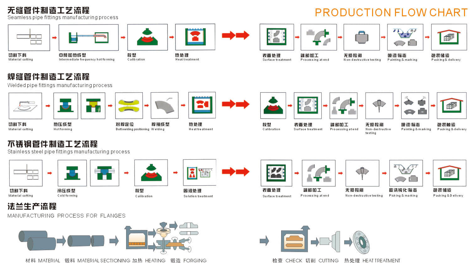
Heating
In order to meet the requirements of material deformation in the forming process, it is necessary to heat the blank when the tube is manufactured by hot forming method. The temperature usually depends on the material and heating process.
During the forming of hot pushing elbow or hot bending elbow, the medium frequency or high frequency induction heating method is usually used, and the flame heating method is also used. This kind of heating mode is continuous heating which is synchronous with the forming process of elbow or elbow. The tube blank is heated in motion and the forming process is completed.
When hot pressing elbow, hot pressing tee or forging are formed, the heating method of reverberatory furnace, flame heating, induction heating or electric furnace heating are usually adopted. This kind of heating is to first heat the tube blank to the required temperature, and then put it into the die for pressing or forging.
Welding
There are two kinds of pipe fittings with welding seam. One is the pipe fittings made of welded pipe. For the pipe fitting manufacturer, the forming process of welded pipe is basically the same as that of seamless pipe, and the forming process of pipe fitting does not include welding process; the other is that the pipe fitting manufacturer completes the welding process required for pipe fitting forming, such as the elbow formed by assembling and welding after single piece pressing The tee pipe is welded into tube blank after being rolled by steel plate drum, etc.
The commonly used welding methods of pipe fittings are manual arc welding, gas shielded welding and automatic welding.
Our factory guides the welding work according to the preparation of the welding procedure specification, and carries out the welding procedure qualification according to the corresponding specification requirements, so as to verify the correctness of the welding procedure specification and evaluate the welding ability of the welder.
One of the most common manufacturing methods for caps, where plate is cut out in a circle and formed by deep drawing.
Deep drawing is the manufacturing process of forming sheet metal stock, called blanks, into geometrical or irregular shapes that are more than half their diameters in depth. Deep drawing involves stretching the metal blank around a plug and then moving it into a moulding cutter called a die.
A drawing press can be used for forming sheet metal into different shapes and the finished shape depends on the final position that the blanks are pushed down in. The metal used in deep drawing must be malleable as well as resistant to stress and tension damage.
In the behavior, we make beveling after shot blasting, bevel ends are fully machined by advanced equipment Double Beveling Machine ensure the height, length, thickness, O.D. and I.D. are all qualified.
Welding Bevel acc. to

The ends of all buttweld fittings are bevelled, exceeding wall thickness 4 mm for austenitic stainless steel, or 5 mm for ferritic stainless steel. The shape of the bevel depending upon the actual wall thickness. This bevelled ends are needed to be able to make a “Butt weld”.
ASME B16.25 covers the preparation of buttwelding ends of piping components to be joined into a piping system by welding. It includes requirements for welding bevels, for external and internal shaping of heavy-wall components, and for preparation of internal ends (including dimensions and dimensional tolerances).
Our in-hourse R&D team developed bevel ends equipment are good using in thickness 2mm to 20mm pipe fittings, guarantee high efficiency and high quality.
| Nominal wall Thickness : t | End Preparation |
|---|---|
| t<5mm (for austenitic alloy steel | Cut square or slightly chamfer |
| t<4mm) | at manufacturer ' s option |
5| Plain Bevel as in sketch ( a ) above |
|
| t>22mm | Compound Bevel as in sketch ( b ) above |
| Nominal pipe | Outside Diameter at Bevel | Center to End | ||||
|---|---|---|---|---|---|---|
| DN size | D1 | D2 | C | M | ||
| Series A | Series B | Series A | Series B | |||
| 20×15 | 26.9 | 25 | 21.3 | 18 | 29 | 29 |
| 25×20 | 33.7 | 32 | 26.9 | 25 | 38 | 38 |
| 25×15 | 33.7 | 32 | 21.3 | 18 | 38 | 38 |
| 32×25 | 42.4 | 38 | 33.7 | 32 | 48 | 48 |
| 32×20 | 42.4 | 38 | 26.9 | 25 | 48 | 48 |
| 32×15 | 42.4 | 38 | 21.3 | 18 | 48 | 48 |
| 40×32 | 48.3 | 45 | 42.4 | 38 | 57 | 57 |
| 40×25 | 48.3 | 45 | 33.7 | 32 | 57 | 57 |
| 40×20 | 48.3 | 45 | 26.7 | 25 | 57 | 57 |
| 40×15 | 48.3 | 45 | 21.3 | 18 | 57 | 57 |
| 50×40 | 60.3 | 57 | 48.3 | 45 | 64 | 60 |
| 50×32 | 60.3 | 57 | 42.4 | 38 | 64 | 57 |
| 50×25 | 60.3 | 57 | 33.7 | 32 | 64 | 51 |
| 50×20 | 60.3 | 57 | 26.9 | 25 | 64 | 44 |
| 65×50 | 76.1(73) | 76 | 60.3 | 57 | 76 | 70 |
| 65×40 | 76.1(73) | 76 | 48.3 | 45 | 76 | 67 |
| 65×32 | 76.1(73) | 76 | 42.4 | 38 | 76 | 64 |
| 65×25 | 76.1(73) | 76 | 33.7 | 32 | 76 | 57 |
| 80×65 | 88.9 | 89 | 76.1(73) | 76 | 86 | 83 |
| 80×50 | 88.9 | 89 | 60.3 | 57 | 86 | 76 |
| 80×40 | 88.9 | 89 | 48.3 | 45 | 86 | 73 |
| 80×32 | 88.9 | 89 | 42.4 | 38 | 86 | 70 |
| 90×80 | 101.6 | - | 88.9 | - | 95 | 92 |
| 90×65 | 101.6 | - | 76.1(73) | - | 95 | 89 |
| 90×50 | 101.6 | - | 60.3 | - | 95 | 83 |
| 90×40 | 101.6 | - | 48.3 | - | 95 | 79 |
| 100×90 | 114.3 | - | 101.6 | - | 105 | 102 |
| 100×80 | 114.3 | 108 | 88.9 | 89 | 105 | 98 |
| 100×65 | 114.3 | 108 | 76.1(73) | 76 | 105 | 95 |
| 100×50 | 114.3 | 108 | 60.3 | 57 | 105 | 89 |
| 100×40 | 114.3 | 108 | 48.3 | 45 | 105 | 86 |
| 125×100 | 139.7 | 133 | 114.3 | 108 | 124 | 117 |
| 125×90 | 139.7 | - | 101.6 | - | 124 | 114 |
| 125×80 | 139.7 | 133 | 88.9 | 89 | 124 | 111 |
| 125×65 | 139.7 | 133 | 76.1(73) | 76 | 124 | 108 |
| 125×50 | 133 | 60.3 | 57 | 124 | 105 | |
| 150×125 | 168.3 | 159 | 139.7 | 133 | 143 | 137 |
| 150×100 | 168.3 | 159 | 114.3 | 108 | 143 | 130 |
| 150×90 | 168.3 | - | 101.6 | - | 143 | 127 |
| 150×80 | 168.3 | 159 | 88.9 | 89 | 143 | 124 |
| 150×65 | 168.3 | 159 | 76.1(73) | 76 | 143 | 121 |
| 200×150 | 219.1 | 219 | 168.3 | 159 | 178 | 168 |
| 200×125 | 219.1 | 219 | 139.7 | 133 | 178 | 162 |
| 200×100 | 219.1 | 219 | 114.3 | 108 | 178 | 156 |
| 200×90 | 219.1 | - | 101.6 | - | 178 | 152 |
| 200×200 | 273 | 273 | 219.1 | 219 | 216 | 208 |
| 200×150 | 273 | 273 | 168.3 | 159 | 216 | 194 |
| 200×125 | 273 | 273 | 139.7 | 133 | 216 | 191 |
| 200×100 | 273 | 273 | 114.3 | 108 | 216 | 184 |
| 300×250 | 323.9 | 325 | 273 | 273 | 254 | 241 |
| 300×200 | 323.9 | 325 | 219.1 | 219 | 254 | 229 |
| 300×150 | 323.9 | 325 | 168.3 | 159 | 254 | 219 |
| 300×125 | 323.9 | 325 | 139.7 | 133 | 254 | 216 |
| 350×300 | 355.6 | 377 | 323.9 | 325 | 279 | 270 |
| 350×250 | 355.6 | 377 | 273 | 273 | 279 | 257 |
| 350×200 | 355.6 | 377 | 219.1 | 219 | 279 | 248 |
| 350×150 | 355.6 | 377 | 168.3 | 159 | 279 | 238 |
| 400×350 | 406.4 | 426 | 355.6 | 377 | 305 | 305 |
| 400×300 | 406.4 | 426 | 323.9 | 325 | 305 | 295 |
| 400×250 | 406.4 | 426 | 273 | 273 | 305 | 283 |
| 400×200 | 406.4 | 426 | 219.1 | 219 | 305 | 273 |
| 400×150 | 406.4 | 426 | 168.3 | 159 | 305 | 264 |
| 450×400 | 457.2 | 478 | 406.4 | 426 | 343 | 330 |
| 450×350 | 457.2 | 478 | 355.6 | 377 | 343 | 330 |
| 450×300 | 457.2 | 478 | 323.9 | 325 | 343 | 321 |
| 450×250 | 457.2 | 478 | 273 | 273 | 343 | 308 |
| 450×200 | 457.2 | 478 | 219.1 | 219 | 343 | 298 |
| 500×450 | 508 | 529 | 457.2 | 478 | 381 | 368 |
| 500×100 | 508 | 529 | 406.4 | 426 | 381 | 356 |
| 500×350 | 508 | 529 | 355.6 | 377 | 381 | 356 |
| 500×300 | 508 | 529 | 323.9 | 325 | 381 | 346 |
| 500×250 | 508 | 529 | 273 | 273 | 381 | 333 |
| 500×200 | 508 | 529 | 219.1 | 219 | 381 | 324 |
| 550×500 | 559 | - | 508 | - | 419 | 406 |
| 550×450 | 559 | - | 457 | - | 419 | 394 |
| 550×400 | 559 | - | 406 | - | 419 | 381 |
| 600×550 | 610 | - | 559 | - | 432 | 432 |
| 600×550 | 610 | 630 | 508 | 530 | 432 | 432 |
| 600×450 | 610 | 630 | 457 | 480 | 432 | 419 |
| 650×600 | 660 | - | 610 | - | 495 | 483 |
| 650×550 | 660 | - | 559 | - | 495 | 470 |
| 650×500 | 660 | - | 508 | - | 495 | 457 |
| 700×650 | 711 | - | 660 | - | 521 | 521 |
| 700×600 | 711 | 720 | 610 | 630 | 521 | 508 |
| 700×550 | 711 | - | 559 | - | 521 | 495 |
| 750×700 | 762 | - | 711 | - | 559 | 546 |
| 750×650 | 762 | - | 660 | - | 559 | 546 |
| 750×600 | 762 | - | 610 | - | 559 | 533 |
| 800×750 | 813 | - | 762 | - | 597 | 584 |
| 800×700 | 813 | 820 | 711 | 720 | 597 | 572 |
| 800×650 | 813 | - | 660 | - | 597 | 572 |
| 850×800 | 864 | - | 813 | - | 635 | 622 |
| 850×750 | 864 | - | 762 | - | 635 | 610 |
| 850×700 | 864 | - | 711 | - | 635 | 597 |
| 900×850 | 914 | - | 864 | - | 673 | 660 |
| 900×800 | 914 | 920 | 813 | 820 | 673 | 648 |
| 900×750 | 914 | - | 762 | - | 673 | 635 |
| 950×900 | 965 | - | 914 | - | 711 | 711 |
| 950×850 | 965 | - | 864 | - | 711 | 698 |
| 950×800 | 965 | - | 813 | - | 711 | 686 |
| 1000×950 | 1016 | - | 965 | - | 749 | 749 |
| 1000×900 | 1016 | 1020 | 914 | 920 | 749 | 737 |
| 1000×8500 | 1016 | - | 864 | - | 749 | 724 |
| 1000×1000 | 1067 | - | 1016 | - | 762 | 711 |
| 1050×950 | 1067 | - | 965 | - | 762 | 711 |
| 1050×900 | 1067 | - | 914 | - | 762 | 711 |
| 1100×1050 | 1118 | - | 1067 | - | 813 | 762 |
| 1100×1000 | 1118 | 1120 | 1016 | 1020 | 813 | 749 |
| 1100×950 | 1118 | - | 965 | - | 813 | 737 |
| 1150×1100 | 1168 | - | 1118 | - | 851 | 800 |
| 1150×1050 | 1168 | - | 1067 | - | 851 | 787 |
| 1150×1000 | 1168 | - | 1016 | - | 851 | 775 |
| 1200×1150 | 1220 | - | 1168 | - | 889 | 838 |
| 1200×1100 | 1220 | 1220 | 1118 | 1120 | 889 | 838 |
| 1200×1050 | 1220 | - | 1067 | - | 889 | 813 |
| Nominal pipe size | Outside Diameter at Bevel | Center to End | |||
|---|---|---|---|---|---|
| D | C | M | |||
| DN | INCH | Series A | Series B | ||
| 15 | 1/2 | 21.3 | 18 | 25 | |
| 20 | 3/4 | 26.9 | 25 | 29 | |
| 25 | 1 | 33.7 | 32 | 38 | |
| 32 | 1 1/4 | 42.4 | 38 | 48 | |
| 40 | 1 1/2 | 48.3 | 45 | 57 | |
| 50 | 2 | 60.3 | 57 | 64 | |
| 65 | 2 1/2 | 76.1(73) | 76 | 76 | |
| 80 | 3 | 88.9 | 89 | 86 | |
| 90 | 3 1/2 | 101.6 | ― | 95 | |
| 100 | 4 | 114.3 | 108 | 105 | |
| 125 | 5 | 139.7 | 133 | 124 | |
| 150 | 6 | 168.3 | 159 | 143 | |
| 200 | 8 | 219.1 | 219 | 178 | |
| 250 | 10 | 273 | 273 | 216 | |
| 300 | 12 | 323.9 | 325 | 254 | |
| 350 | 14 | 355.6 | 377 | 279 | |
| 400 | 16 | 406.4 | 426 | 305 | |
| 450 | 18 | 457.2 | 478 | 343 | |
| 500 | 20 | 508 | 529 | 381 | |
| 550 | 22 | 559 | ― | 419 | |
| 600 | 24 | 610 | 630 | 432 | |
| 650 | 26 | 660 | ― | 495 | |
| 700 | 28 | 711 | 720 | 521 | |
| 750 | 30 | 762 | ― | 559 | |
| 800 | 32 | 813 | 820 | 597 | |
| 850 | 34 | 864 | ― | 635 | |
| 900 | 36 | 914 | 920 | 673 | |
| 950 | 38 | 965 | ― | 711 | |
| 1000 | 40 | 1016 | 1020 | 749 | |
| 1050 | 42 | 1067 | ― | 762 | 711 |
| 1100 | 44 | 1118 | 1120 | 813 | 762 |
| 1150 | 46 | 1168 | ― | 851 | 800 |
| 1200 | 48 | 1220 | 1220 | 889 | 838 |
Pipe and pipe fittings go hand-in hand. Just as pipes are used for a variety of residential, public and industrial applications, so also the pipe fittings. No pipes can be connected without the use of proper fittings and flanges. Pipe fittings allow pipes to be installed and connected or joined where necessary and terminated in the right place.

Such as Oil and gas industries, Midstream, Shipbuilding, Power plants, Food plants, Pharmaceuticals, etc.
Pipe fittings include a wide range of products in various shapes, sizes and materials. With rapid developments in the field of industrial fittings and continuous research work in this industry, various new products are manufactured. Some fittings have certain special features so that they can be fabricated on different principles like hydraulics, pneumatic depending on the end usage.
Fittings include a comprehensive range of products depending on various applications in which they are applied.
Fittings are used wherever liquids, gases, chemicals and other fluids are created, processed, transported, or used.
There is no end to applications of pipe fittings so long there is no end to the applications of pipes . While the list of piping applications continues to expand, its strength, flexibility, very good flow rates and high chemical resistance are qualities which are uniquely suited for the movement or transfer of liquids, steam, solids and air from one point to another.
With piping, pipe fittings have many other uses like as follows:
In all the above-mentioned industries pipes are used to transfer liquid, gas, slurries, and other solids and fluids from one area to another and accordingly different categories of pipe fittings are used . Thus, pipe fittings play a vital role for proper functioning of pipe and tubes in various applications.
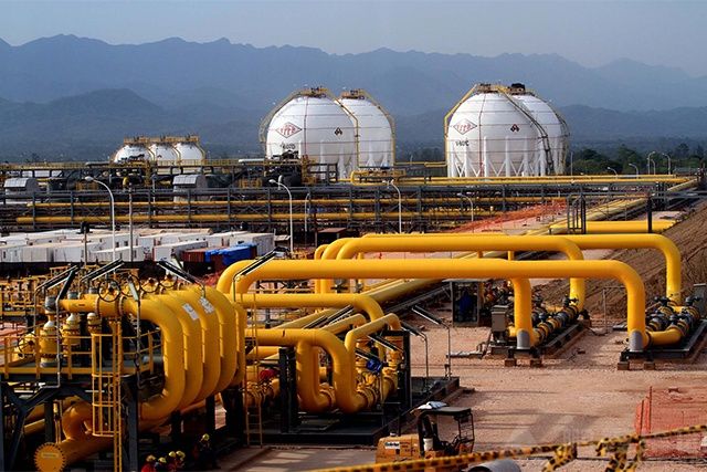
The chemical equipment refers to the process piping used for the downstream processing equipment of refining ethylene. There are carbon steel pipes and stainless steel pipes (seamless and welded): the commonly used carbon steel pipes are made of 20# (GB/T8163) and 20G (GB5310). 20g and 20# (GB9948) are rarely used. If it is used for Class A pipes, it must be 100% UT; the steels commonly used for stainless steel pipes are generally 304, 316L, 316Ti, etc.
The four major pipelines of the power plant include:
1: main steam pipe (two high temperature and high pressure steam pipes between the superheater outlet header and the high pressure main steam port);
2: hot reheat steam pipe (two high temperature and high pressure steam pipes from the reheater outlet header to the medium pressure main valve port);
3: cold reheat steam pipe (two high temperature and high pressure steam pipes between the high pressure cylinder exhaust port and the reheater inlet header interface);
4: High-pressure water supply pipe (electric water supply pump outlet to the high-pressure boiler supply water pipe between the economizer inlet header interface).
And four high-pressure pipes and fittings (elbows, flanges, tees, large and small heads, elbows) for pipelines.

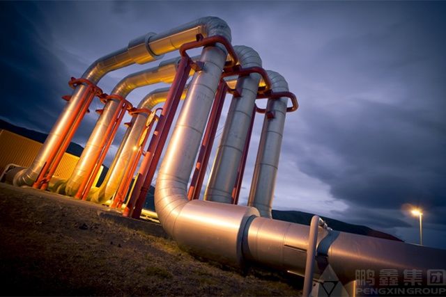
Heating polyurethane insulated steel pipe insulation pipe is widely used in liquid and gas transportation pipe network, chemical pipeline insulation engineering petroleum, chemical, centralized heating and heating network, central air conditioning ventilation pipe, municipal engineering, etc. The high temperature prefabricated direct buried thermal insulation pipe is a direct buried prefabricated thermal insulation pipe with good thermal insulation performance, safe and reliable, and low engineering cost. It effectively solves the problem of insulation, sliding lubrication and waterproofing of the pipe end of the prefabricated direct buried thermal insulation pipe for 130°C-600°C high temperature heat transfer in urban central heating.
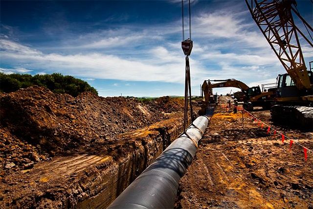
The oil and gas pipelines are assembled by a single pipe connected one by one. The modern oil and gas pipelines and oil and gas pipelines are made of steel pipes connected by electric welding. The steel pipe has a variety of seamless pipes, spiral seam pipes and straight seam pipes. The seamless pipe is suitable for pipes with a pipe diameter of 529 mm or less, and the spiral seam pipe and the straight seam pipe are suitable for large diameter pipes. The cross-sectional structure of the pipe of the gathering pipeline is complicated by the inner coating-steel pipe-outer insulation layer-insulation (cooling) layer; the simple one is only the steel pipe and the outer insulation layer, while the inner wall coating and the heat preservation (cold insulation) layer are both considered The oil and gas transfer process will be determined.

The ship pipeline is a pipe used to connect various mechanical equipment on the ship to transport water, oil, gas and other related working fluids. There are two main types of ship pipelines: power pipelines and ship system pipelines. The power line is used for various pipelines for the main engine and the auxiliary machine. It has fuel, oil, cooling water, compressed air, exhaust gas, waste heat and other pipelines. The ship system pipeline is to improve the ship’s anti-sinking and stability, in order to meet the normal living needs of the crew and passengers.
Drilling platform piping can be divided into: bilge piping, ballast piping, ventilation piping, fire piping, daily water piping, drilling water piping, compressed air piping, fuel piping, oil piping, Hydraulic transmission pipe system, steam pipe system, boiler feed water sewage condensate pipe system, sea water (cooling water) pipe system, exhaust pipe system, solid control pipe system, mud pipe system, ash conveying pipeline system, punching pile pipe system, etc. And other uses
For packing of carbon steel flanges with painting,we would use the bubble wrap to protect the painting.For flanges without painting or oiled with long-term shipment,we would suggest client to use the anti-tarnish paper and plastic bag to prevent the rust.
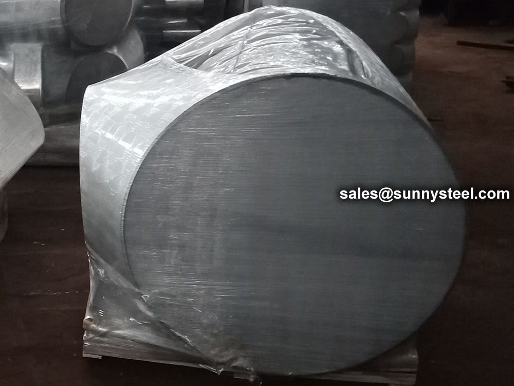
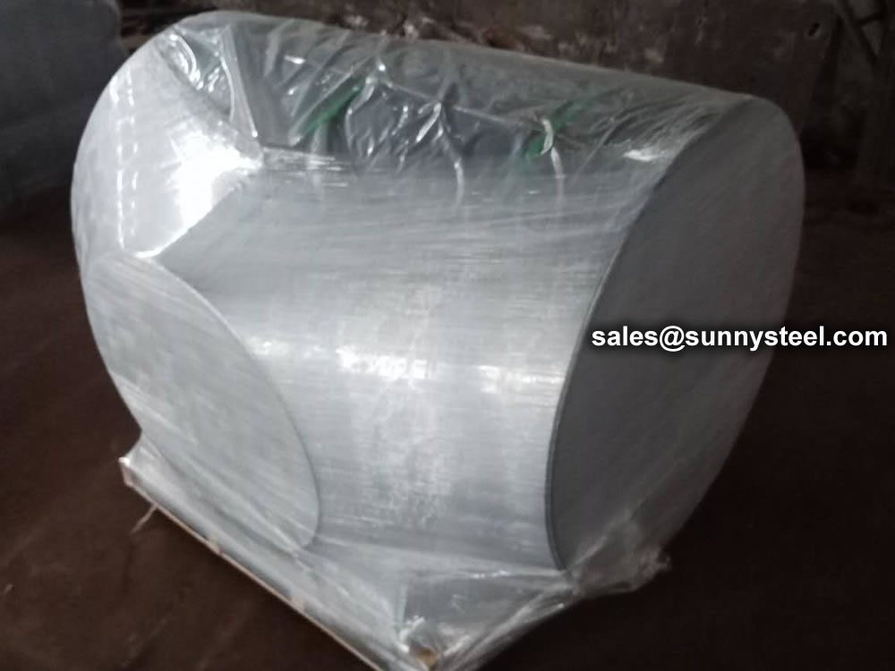
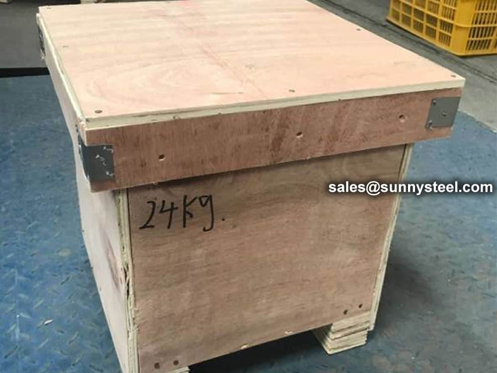
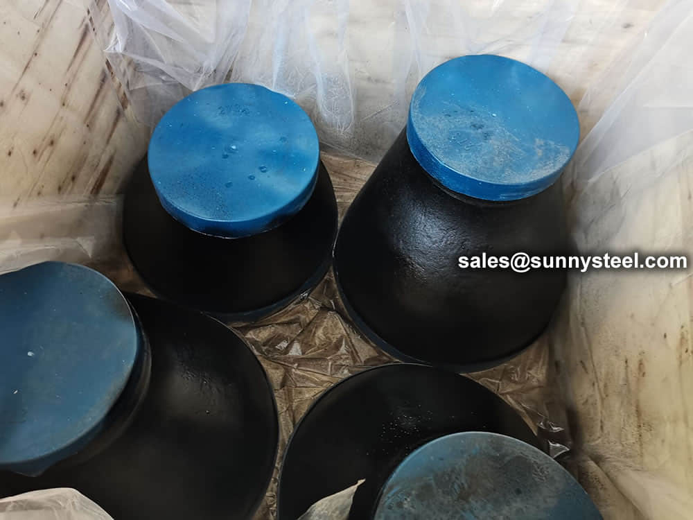 Packing reducers in wooden cases
Wrap the plastic tightly around the pipe to protect the tee
Need to inquire about our products? Fill out the form below and our staff will be in touch!
Q: How long is your delivery time? A: The delivery time of customized products is generally 25 35 days, and non customized products are generally shipped within 24 hours after payment. Q: Do you provide samples? Is it free? A: If the value of the sample is low, we will provide it for free, but the freight needs to be paid by the customer. But for some high value samples, we need to charge a fee. Q: What are your payment terms? A: T/T 30% as the deposit,The balance payment is paid in full before shipment Q: What is the packaging and transportation form? A: Non steaming wooden box and iron frame packaging. Special packaging is available according to customer needs. The transportation is mainly by sea. Q: What is your minimum order quantity? A: There is no minimum order quantity requirement. Customized products are tailor made according to the drawings provided by the customer.


