Our team is highly trained and experienced in servicing and producing all types of steel supplies. Need help or have a question?
sales@abrasionresistantpipe.com
Tel.: +8621-3378-0199
Our team is highly trained and experienced in servicing and producing all types of steel supplies. Need help or have a question?
sales@abrasionresistantpipe.com
Tel.: +8621-3378-0199


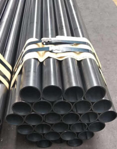
A carbon steel ERW pipe is a high carbon grade of steel. Carbon steel ERW pipe is manufactured as metal rolled and welded longitudinally.
A carbon steel ERW pipe is a high carbon grade of steel. Carbon steel ERW pipe is manufactured as metal rolled and welded longitudinally.
ERW steel pipe is formed by rolling plate and welding the seam.
| Product Name | Executive Standard | Dimension (mm) | Steel Code / Steel Grade |
| Casting | API 5CT | Ø48.3~273 x WT2.77~11.43 | J55, K55, N80, L80 |
| Tubing | API 5CT | Ø48.3~273 x WT2.77~11.43 | J55, K55, N80, L80, H40 |
| Line Pipes | API 5L | Ø60.3~273.1 x WT2.77~12.7 | A25, A, B, X42, X46, X52, X56, X60, X65, X70, X80 |
| Electric-Resistance-Welded Steel Pipes | ASTM A135 | Ø42.2~114.3 x WT2.11~2.63 | A |
| ERW and Hot-dip Galvanized Steel Pipes | ASTM A53 | Ø21.3~273 x WT2.11~12.7 | A, B |
| Pipes for Piling Usage | ASTM A252 | Ø219.1~508 x WT3.6~12.7 | Gr.2, Gr.3 |
| Tubes for General Structural Purpose | ASTM A500 | Ø21.3~273 x WT2.11~12.7 | Gr.2, Gr.3 |
| Square Pipes for General Structural Purpose | ASTM A500 | 25 x 25~160 x 160 x WT1.2~8.0 | Carbon Steel |
| Threaded Steel Pipes | DIN 2440 | Ø21~164 x WT2.65~4.85 | Carbon Steel |
| Screwed and Socketed Steel Tubes | BS 1387 | Ø21.4~113.9 x WT2~3.6 | Carbon Steel |
| Scaffolding Pipes | EN 39 | Ø48.3 x WT3.2~4 | Carbon Steel |
| Carbon Steel Tubes for General Structure Purpose | JIS G3444 | Ø21.7~216.3 x WT2.0~6.0 | Carbon Steel |
| Carbon Steel Tubes for Machine Structure Purpose | JIS G3445 | Ø15~76 x WT0.7~3.0 | STKM11A, STKM13A |
| Carbon Steel Pipes for Ordinary Piping | JIS G3452 | Ø21.9~216.3 x WT2.8~5.8 | Carbon Steel |
| Carbon Steel Pipes for Pressure Service | JIS G3454 | Ø21.7~216.3 x WT2.8~7.1 | Carbon Steel |
| Carbon Steel Rigid Steel Conduits | JIS G8305 | Ø21~113.4 x WT1.2~3.5 | G16~G104, C19~C75, E19~E75 |
| Carbon Steel Rectangular Pipes for General Structure | JIS G3466 | 16 x 16~150 x 150 x WT0.7~6 | Carbon Steel |
A CS ERW pipe has exceptional dimensional accuracy coupled with good mechanical properties. Furthermore, the production and smelting process is simple and low cost. The steel erw pipes have uniform wall thicknesses with high concentricity.
The equipment required to weld the ERW pipes requires higher capital and manpower. Its maintenance is tricky, and there are little to no non-destructive methods to monitor the reliability of the weld. Lastly, the seams decrease the tensile and fatigue strength of the workpiece.
Carbon steel pipes can be welded to different specifications to suit different requirements.
 Features of ERW pipe
Low cost: the low raw material cost and manufacturing cost make it prices more competitive than longitudinal seam submerged-arc welded pipes and seamless pipes.
High Weld Seam Security: As a result of special welding method of melting parent metal together, without filler metal, the weld property is better than submerged-arc welded pipes; and the weld seam is much shorter than spiral seam welded pipes, the seam security is greatly improved.
Wide Range: ERW pipes can be applied with a wide range of thickness / diameter ratio, covering hundreds of specifications.
This article provides an overview of electric resistance welding (ERW). It dicusses high-frequency ERW (contact and induction) and rotary wheel contact welding (AC, DC, and square wave). It describes the differences among the processes, as well as the power supplies and weld rolls.
Several electric resistance welding (ERW) processes are available for tube and pipe production. While each process has different characteristics, all ERW processes have one thing in common–all of them produce a forged weld.
A forged weld is created by applying a combination of heat and pressure, or forging force, to the weld zone. A successful forged weld uses the optimum amount of heat, which is normally slightly less than the melting point of the material, and a nearly simultaneous application of circumferential pressure to the section, which forces the heated edges together (see Figure 1).
As the name implies, the heat generated by the weld power is a result of the material’s resistance to the flow of electrical current. The pressure comes from rolls that squeeze the tube into its finished shape.
The two main types of ERW are high-frequency (HF) and rotary contact wheel.

The two main aspects of HF welding are processes and power supplies. Each of these can be broken down further into subcategories. Processes. The two HF welding processes are HF contact and HF induction. In both processes, the equipment that provides the electrical current is independent from the equipment that supplies the forge pressure. Also, both HF methods can employ impeders, which are soft magnetic components located inside the tube that help to focus the weld current in the strip edges.

HF Induction Welding. In the case of HF induction welding, the weld current is transmitted to the material through a work coil in front of the weld point (see Figure 2). The work coil does not contact the tube–the electrical current is induced into the material through magnetic fields that surround the tube. HF induction welding eliminates contact marks and reduces the setup required when changing tube size. It also requires less maintenance than contact welding.
It is estimated that 90 percent of tube mills in North America use HF induction welding.
HF Contact Welding. HF contact welding transfers weld current to the material through contacts that ride on the strip (see Figure 3). The weld power is applied directly to the tube, which makes this process more electrically efficient than HF induction welding. Because it is more efficient, it is well-suited to heavy-wall and large-diameter tube production.
Power Supplies. HF welding machines also are classified by how they generate power. The two types are vacuum tube and solid-state. The vacuum tube type is the traditional power supply. Since their introduction in the early ’90s, however, solid-state units have quickly gained prominence in the industry. It is estimated that between 500 and 600 of each type are operating in North America.
In rotary contact wheel welding, the electrical current is transmitted through a contact wheel at the weld point. The contact wheel also applies some of the forge pressure necessary for the welding process.
The three main types of rotary contact wheel welders are AC, DC, and square wave. In all three power supplies, electrical current is transferred by brush assemblies that engage slip rings attached to a rotating shaft that supports the contact wheels. These contact wheels transfer the current to the strip edges.
AC Rotary Contact Wheel Welding. In an AC rotary contact wheel welding machine, the current is transferred through the brushes to the rotating shaft, which has a transformer mounted on it. The transformer reduces the voltage and increases the current, making it suitable for welding. The two legs of the transformer’s output circuit are connected to the two halves of the rotating contact wheel, which are insulated from each other. The strip completes the circuit by acting as a conductor between the two halves of the wheel.
Traditional rotary contact wheel welders used 60-hertz AC, or common line current. A drawback to this system is that the current–and therefore the weld heat–rises and falls, limiting the speed at which the tube can be welded. An AC sine wave reaches its maximum amplitude briefly, producing weld heat that varies just as the sine wave does (see Figure 4).

To help even out the heat variation, motor generator sets were introduced to create AC at higher frequencies. Some of the frequencies used were 180, 360, 480, and 960 Hz. A few solid-state units also were produced to generate higher-frequency currents. An AC sine wave at 960 Hz reaches its maximum amplitude 1,920 times per second, as opposed to 120 times per second with a 60-Hz signal. The 960-Hz sine wave produces heat with a much more consistent temperature.
DC Rotary Contact Wheel Welding. The next step in rotary contact wheel welding was the DC power supply. The power produced has a nearly constant amplitude. Although this solves the problem of varying heat, a major drawback is that higher maintenance costs are associated with this type of welding machine.
Because it is not possible to change the voltage of DC with a transformer, it is necessary to transmit the high-amperage, low-voltage weld current into the shaft through a large number of brushes (92 for DC versus 8 for AC) with a high current density. Transmitting high-amperage, low-voltage current produces excess (waste) heat that causes heavy wear, resulting in the high maintenance costs mentioned previously.
Square Wave Rotary Contact Wheel Welding. The latest step in the evolution of rotary contact wheel welding is the square wave power supply. This method combines the consistent weld heat of DC with the lower maintenance associated with AC units (see Figure 5). While rotary contact weld methods preceded the more commonly used HF welding processes, they still have a vital role in specialty welding applications. Rotary contact welding is useful for applications that cannot accommodate an impeder on the ID of the tube. Examples of this are small-diameter refrigeration-grade tube and tube that is painted on the ID immediately after the welding process.
The types of weld pressure rolls, or squeeze boxes as they sometimes are called, that apply the pressure required for the weld are as varied as the welding units used to supply the heat. Squeeze boxes for rotary contact wheel welding typically have two or three roll units, with the contact wheel serving as one of the rolls.
The number of rolls in the weld squeeze box is proportionate to the size and shape of the product being welded. There are no hard and fast rules; however, common guidelines for round tube or pipe size ranges are as follows:
Today, much more so than in the past, many shapes–square, rectangular, hexagonal–are welded in the finished shape rather than being reshaped after being welded round. The weld boxes used for the shapes are custom-designed for each application and usually have no more than five rolls.
While manufacturing ERW steel pipes, only high-quality, continuous-cast, fully killed, control-rolled, fine-grain, low-carbon steel is used.
ERW steel pipes are manufactured by low-frequency or high-frequency resistance “resistance”.

| Product Name | Executive Standard | Dimension (mm) | Steel Code / Steel Grade |
|---|---|---|---|
| Electric-Resistance-Welded Steel Pipes | ASTM A135 | 42.2-114.3 x 2.11-2.63 | A |
| Electric-Resistance-Welded Carbon Steel and Carbon-Manganese Steel Boiler and Superheater Tubes | ASTM A178 | 42.2-114.3 x 2.11-2.63 | A, C,D |
| ERW and Hot-dip Galvanized Steel Pipes | ASTM A53 | 21.3-273 x 2.11-12.7 | A, B |
| Pipes for Piling Usage | ASTM A252 | 219.1-508 x 3.6-12.7 | Gr2, Gr3 |
| Tubes for General Structural Purpose | ASTM A500 | 21.3-273 x 2.11-12.7 | Carbon Steel |
| Square Pipes for General Structural Purpose | ASTM A500 | 25 x 25-160 x 160 x 1.2-8.0 | Carbon Steel |
| Mechanical tubing | ASTM A513 | 21.3-273 x 2.11-12.7 | carbon and alloy steel |
| Screwed and Socketed Steel Tubes | BS 1387 | 21.4-113.9 x 2-3.6 | Carbon Steel |
| Scaffolding Pipes | EN 39 | 48.3 x 3.2-4 | Carbon Steel |
| Carbon Steel Tubes for General Structure Purpose | JIS G3444 | 21.7-216.3 x 2.0-6.0 | Carbon Steel |
| Carbon Steel Tubes for Machine Structure Purpose | JIS G3445 | 15-76 x 0.7-3.0 | STKM11A, STKM13A |
| Carbon Steel Pipes for Ordinary Piping | JIS G3452 | 21.9-216.3 x 2.8-5.8 | Carbon Steel |
| Carbon Steel Pipes for Pressure Service | JIS G3454 | 21.7-216.3 x 2.8-7.1 | Carbon Steel |
| Carbon Steel Rigid Steel Conduits | JIS G8305 | 21-113.4 x 1.2-3.5 | G16-G104, C19-C75, E19-E75 |
| Carbon Steel Rectangular Pipes for General Structure | JIS G3466 | 16 x 16-150 x 150 x 0.7-6 | Carbon Steel |
Pipeline coating is the most consistent and successful solution for protecting ERW pipes from corrosion, from moisture, other harmful chemicals.
Anti-corrosion steel pipe is processed through the preservation process, which can effectively prevent or slow down the process in the transport and use of chemical or electrochemical corrosion reaction of steel pipe.
Therefore pipe anti-corrosion layer is an important barrier to prevent soil erosion. A well-known foreign scholar put forward” 3PE france protective layer”, so far, anti-corrosion methods is widely used.
Coated pipes offer high resistance to corrosion on pipes and provide many benefits such as:
1. Increased Flow Capacity – A coating on pipes helps provide a smoother surface thus improving gas and liquid flow within pipes.
2. Reduced Cost – The pipeline coating increases the pipes durability so they can be deployed with minimum maintenance cost even in the harshest environments.
3. Lower energy usage – Various studies have shown that pipelines that are internally coated use less energy for pumping and compression of products through pipes. This helps in increased saving over time.
4. Clean delivery of products – The inhibitors used for the protection products can also be minimized by the use of coated pipes for delivery of products.
Thus, coating of pipelines can help you in reducing your maintenance cost and at the same time providing a corrosion free reliable protection.
The basic principles of urban gas pipeline coating selection:
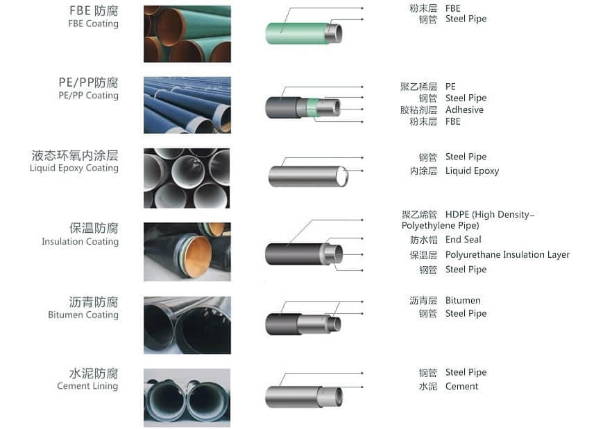
2.1.External Coating
2.1.1 External Epoxy Coating
2.1.2 Polyethylene Coating
2.1.3 Polypropylene Coating
2.1.4 Polyurethane Coating
2.1.5 Polyolefin Coating
2.1.6 Tape Coating
2.1.7 Bitumen Coating
2.1.8 Coal-Tar Enamel Coating
2.1.9 Concrete Weighted Coating
5:External concrete coating.
2.1.10 Marine Coating
2.1.11 Other specification
2.2. Lining
2.2.1 Epoxy Lining
2.2.2 Bitumen Lining
2.2.3 Cement Mortar Lining
2.2.4 Shop Cement Lined Piping
Pipe Coating Products
Three Layer Polyethylene (3LPE)
To improve anticorrosion performance and adhesion, an additional layer of epoxy primer is sprayed onto pipe surfaces prior to the adhesive layer and Polyethylene top layer application. Three Layer Polyethylene is suitable for service temperatures from 60°C to 80°C (85°C peaks). Typical coating thickness is from 1-2 mm to 3-5 mm.
Three Layer Polypropylene (3LPP)
If a wider service temperature range and high stiffness is required, adhesive and top layers, applied over primer layer, are based on polypropylene instead of polyethylene. Three Layer Polypropylene is suitable for service temperatures up to 135 °C (140°C peaks). Typical coating thickness is from 1-2 mm to 3-5 mm.
Three Layer Polypropylene and Polyethylene
Three Layer applications involve a thermoplastic coating applied to steel pipelines as a form of anticorrosion protection. This mechanical resistance is appropriate when the risk of particularly severe coating damages exist. The Three Layer process involved several steps. First, the pipe surface is blast cleaned to remove any external residue from the mill or storage. It is then heated and sprayed with a Fusion Bond Epoxy (FBE) primer followed by the application of an adhesive copolymer and polyolefin polymers that are wrap extruded, one over the other.
Field applied products
Advantage of ERW pipe
The alloy content of the coil is often lower than similar grades of steel plate, improving the weldability of the spiral welded pipe. Due to the rolling direction of spiral welded pipe coil is not perpendicular to the pipe axis direction, the crack resistance of the spiral welded pipe materials.
Need to inquire about our products? Fill out the form below and our staff will be in touch!
Q: How long is your delivery time?
A: The delivery time of customized products is generally 25 35 days, and non customized products are generally shipped within 24 hours after payment.
Q: Do you provide samples? Is it free?
A: If the value of the sample is low, we will provide it for free, but the freight needs to be paid by the customer. But for some high value samples, we need to charge a fee.
Q: What are your payment terms?
A: T/T 30% as the deposit,The balance payment is paid in full before shipment
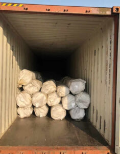
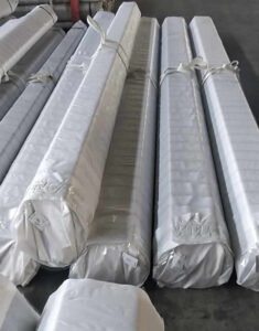
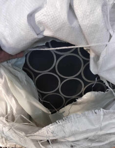
Q: What is the packaging and transportation form?
A: Non steaming wooden box and iron frame packaging. Special packaging is available according to customer needs. The transportation is mainly by sea.
Q: What is your minimum order quantity?
A: There is no minimum order quantity requirement. Customized products are tailor made according to the drawings provided by the customer.


