Our team is highly trained and experienced in servicing and producing all types of steel supplies. Need help or have a question?
sales@abrasionresistantpipe.com
Tel.: +8621-3378-0199
Our team is highly trained and experienced in servicing and producing all types of steel supplies. Need help or have a question?
sales@abrasionresistantpipe.com
Tel.: +8621-3378-0199


The 5D bend in pipe bending is an accomplishment in pipe manufacturing, and not all pipe companies can provide it. The only alternative to finding a professional expert in 5D bends would be to attempt training your current employees to prepare the 5D bends for your business in-house.
The 5D bend in pipe bending is an accomplishment in pipe manufacturing, and not all pipe companies can provide it. The only alternative to finding a professional expert in 5D bends would be to attempt training your current employees to prepare the 5D bends for your business in-house.
The RADIUS of a 5D pipe bend is actually what is 5 times the nominal diameter. So if you had a 10″ diameter pipe, the radius of the centerline of the bend would be 50 inches.

It is the radius of bend of the elbow with reference to a point,the point is determined by the intersection of two lines from the elbows socket end (which makes the shape of one quater of a circle). The bend ie; 1.5d,3d,5d,12d is determined from that point of intersection as a multiple of elbows diameter.
The 5D bend in pipe bending is an accomplishment in pipe manufacturing, and not all pipe companies can provide it.
The only alternative to finding a professional expert in 5D bends would be to attempt training your current employees to prepare the 5D bends for your business in-house. The cost outlay for this undertaking would be prohibitive, however, plus the advantages of having a self-trained 5D bender–versus hiring a professional company with experts who have been creating 5D bends for years–are practically non-existent. Hiring a professional to create the 5D bends piping for your business contracts is a win-win solution. The mere accident potential in having a newbie bending 5Ds is an insurance company’s statistical nightmare. It’s important to find a balance between finding a company that can provide you with what you want, at a price that you can afford. Contacting a company to find out what they are going to charge for 5d bending is critical. When you look at the bending, be specific as to anything else you may need from this company as well, including how much rolled pipe. The more you buy, the more affordable it can be.
The 5D bend in pipe bending is an accomplishment in pipe manufacturing, and not all pipe companies can provide it. The only alternative to finding a professional expert in 5D bends would be to attempt training your current employees to prepare the 5D bends for your business in-house. The cost outlay for this undertaking would be prohibitive, however, plus the advantages of having a self-trained 5D bender–versus hiring a professional company with experts who have been creating 5D bends for years–are practically non-existent. Hiring a professional to create the 5D bends piping for your business contracts is a win-win solution. The mere accident potential in having a newbie bending 5Ds is an insurance company’s statistical nightmare.
It’s important to find a balance between finding a company that can provide you with what you want, at a price that you can afford. Contacting a company to find out what they are going to charge for 5d bending is critical. When you look at the bending, be specific as to anything else you may need from this company as well, including how much rolled pipe. The more you buy, the more affordable it can be.
While the industry provides various means for bending the carbon steel pipe to the 5D bend, heat induction is the most widely-known–but not the most popular–technique in the industry. The pipe to be bent is subjected to extreme temperature, and when at the desired heat, a mode or model in the dimensions of the 5D bends is forced through the heated pipe, causing the pipe to conform to the bend of the 5D pipe dimensions. Carbon steel is the hardest pipe material used in this manner, and heat induction is the best means to curve the carbon steel pipe into the 5D curvature.
Uses
Heat-processed 5D bend pipes are used in all oil and gas lines, and the factory testing exceeds the quality standards required by the oil and gas industry. This is an industry where quality standards can be linked to safety standards.
What You Are Buying
Customers obtain a wide range of bend geometries and total design flexibility with customized radius and angle. Qualified subcontractors carry out hot induction bending with state-of-the-art technology, giving full control of the bending process, as well as total monitoring of all bending parameters.
1) Heat Induction Bends for Oil and Gas Industry
The production of high-quality bends depends on the manufacturing process of the steel pipe that is transformed into the bend. During the hot-induction bending process, unavoidable thinning occurs. Therefore, a custom- and precision-made mother pipe must be produced in order to comply with minimum wall thickness after the bending is complete.
Heat treatment is carried out on each bend in order to achieve the required degree and mechanical properties after bending. For critical applications (such as high-strength steel, heavy wall, sour service or low-temperature) full quenching and tempering after bending is still performed as a preferred process. Machining the bend ends guarantees top tolerances of inside diameters of the pipe. We therefore ensure the bend has the minimum working strengths of the mother pipe.
World-class bending manufacturers provide high quality bending solutions for oil and gas pipelines, either onshore or offshore. The bends manufacturing and testing procedures exceed all quality standards required by the oil and gas industry.
2) Cold Bending Process
High quality bending solutions are more than critical. Cold-bending is commonly used over hot-bending because certain types of steel and metal alloys can be weakened. You cannot allow the pipes to be weakened in any way as this can lead to damage of your product, your plant, or cause risks of injury to your employees. Cold-bending is also preferred by many industries because of its affordability, with costs being less than that of heat induction.
Cold-bending 5D bends is a continuous operation where a long strip of metal, usually steel, is passed through sets of rollers, with each set of rollers performing only a part of the bend, until the desired cross-section profile is obtained. Roll-forming is ideal for producing parts with long lengths or in large quantities. Roll-Forming is also generally a lower cost process than other metal forming processes. Cold-processed bends are used in construction, water piping and as machinery parts.
Sunny Steel provides fast, dependable metal custom-bending for:
We specialize in bending, fabricating and testing of heating and cooling coils. We are proud of our leading reputation in the industry with our attitude of professional workmanship and on-time delivery. Some of our advantages over competitors include:
Sunny Steel fabricates all types and sizes of cooling coils from 1/8″ pipe to 8″ pipe and all alloys.


3D or 5D Pipe Fittings are always use for pipeline connection, the difference is the radius. it can be divide to 3D,5D,6D,7D,10D etc.
3D pipe bending is a pipe bend that the bend radius is 3 times the pipe outside diameter. The RADIUS of a 5D pipe bend is actually what is 5 times the nominal diameter. So if you had a 10″ diameter pipe, the radius of the centerline of the bend would be 50 inches.
Larger numbers have smoother curves. Smoother curves are often used for applications with higher pressure, abrasion or corrosion.
Bends are always part of piping systems. Where standard fittings do not work, induction bends are the next best option. Induction bends in particular meet the demands of stringent technical requirements: Heavy wall, post-bend heat treatment, quenching & tempering, tangents with beveled ends etc.
Bends are made from straight pipe. Common bending radii are 3 and 5 times the pipe size (3R and 5R bends, where R=Nominal Pipe Size – nominal diameter – not radius). 3R bends are available from stock. Larger bends can be custom made, preferably by hot bending. Only seamless or electric-resistance-welded pipe is suitable for bending.
Although 1D and 1.5D bends are readily standard and available within the industry, these particular bends radii will not suit every need, thus 3D and 5D bends differ from the 1D or 1.5D industry standard.
The “D” represents the outside diameter of the pipe, measured in inches, The bends radius is then multiplied by the outside diameter to indicate the type of bend to be made. 3D and 5D Bends are significantly larger than the standard. resulting in larger radius to serve a variety of purposes.
Pipe bends are used in many industries, including chemical, oil and gas, electric, metallurgy and shipbuilding. Pipe bends function as structural passageways to facilitate the transfer of substances, such as water and fuel. Some have a short radius while others have a long radius. Long radius bends give less frictional resistance and allow for less pressure drop when compared to short radius bends. When selecting the type of pipe bend, it’s important to choose one that is compatible to the application.
Bend pipes come in all types of radii, including 3D bends, 4D bends, 5D bends, 8D bends and 10D bends. The radius in 5D bends is five times the nominal diameter. With a 10-inch diameter pipe, the radius of the centerline of the bend would be 50 inches. Pipe bending for the specified radii is both art and science. And with today’s modern machines and advanced software, pipe bending is highly precise. With the right machine, lubrication, tooling and material, achieving the perfect bend is a sure thing.
Although the words bends and elbows are often used as synonyms, there are some differences. Bend is a term for any offset of direction in the piping while elbow is an engineering term. Elbows have limitations to angle, bend radius and size. Most angles are either 45 degrees or 90 degrees. All other offsets are specifically pipe bends. And while elbows have sharp corners, bends never do. The most basic different between a bend and an elbow is the radius of curvature. Bends have a radius more than twice the diameter, and elbows have a radius of curvature between one and two times the size of the pipe’s diameter. All elbows are bends, but not all bends are elbows.
Induction bending is one of the means of bending pipes for 5D and other bends. Local heating, using high-frequency induced electrical power, is applied. An induction coil is placed around the pipe and heats a circumferential area of the pipe at a temperature between 850 to 1100 degrees Celsius. When the right temperature is reached, the pipe moves through an induction coil while an arm applies the bending force. There are many benefits to induction bending. It allows for large radii for smooth flow of fluid, reduces the number of welds in a system and fabricates bends quickly. With faster production, efficiency is ramped up. It’s also a clean process, as no lubrication is needed, and water is recycled.
Ram-type bending is an old and effective bending method for bending pipes, including 4D bends and 5D bends. This method is often used in muffler shops. It’s also one of the least expensive ways to bend pipe. A hydraulically driven ram forces the pipe against pivot blocks or rollers. Often, a ram tool is used to produce a concave surface and to prevent stretching on the exterior of the bend. The only downside is that ram-type bending is not as controllable as other methods.
Roll bending is commonly used for pipes in the construction industry. Rolls are positioned vertically or horizontally to produce very large radii. The pinch-style roll bender is one of the machine types used for roll bending. A tube feeds between the lower and upper roll to produce the wanted bend angle. Some applications may require an additional roll to guide the tube outward when the coil is being formed.
The mandrel bending pipe method is effective when the least amount of deformation is desired. The pipe is supported with a mandrel support to bend the pipe. The pipe is drawn through a counter bending die for further bending. This method of pipe bending is used in the manufacture of heat exchanger tubing, dairy tubing and exhausts like turbocharger and custom made ones. This method produces a non-deformed diameter every time.
Rotary draw bending is often used for bending pipe when a constant diameter and good finish are desired. The pipe is drawn through a stationary counter-bending die onto a fixed radius former die. It’s used for roll cages, stock car chassis and other types of pipes.
Centerline radius, outside diameter and wall thickness are important variables with bending pipe methods. Plus, every pipe schedule has a nominal wall thickness. And since wall thickness can vary, any variations need to be accounted for. Other bending variables include the neutral line, outside bend radius and inside bend radius. Pipes experience spring back after bending. The harder the pipe and small the bend’s centerline radius, the more spring back, which results in radial growth. Copper pipes have less radial growth than steel pipe due to its less spring back. In pipe bending, consistency, size and quality of the weld seam matter for centerline radius, outside diameter and wall thickness. When these are right, the perfect bend can be created.
Common materials used for pipes and pipe bends include carbon, stainless steel, titanium, aluminum and cast iron. There are also plastic pipes of various grades. It’s important to select the right material for the right application, including the pipe fittings. Pipe fitting materials include aluminum, brass, bronze, cast iron, vitrified clay and many others. Pipe fittings must satisfy many criteria. The materials must be compatible with the fluids being transported, different pressure levels and fluctuating temperatures. Materials should also conform to certain standards like DIN, ASME, NPT and BSP. Surface finish is also important, and pipe fittings should have a corrosion-resistant property.
In some fields, the schedule 40 and schedule 80 are used for pipes. However, there are many other schedules due to increased pressure demands. The schedule of a pipe refers to its pressure rating. The higher the schedule, the higher pressure it can have. As the schedule increases, the wall thickness increases. When choosing pipe bends, it is critical to consider the schedule of the pipe. Schedule 80 is often used for heavy-duty while schedule 40 is often used for light-duty. Be sure to choose the appropriate schedule for the pipe bend, and it will be a perfect match.
Any time that you are going to get 5D bends, you want to know about your options and the overall process. Getting involved ensures your specifications are met and that the bends are durable enough to last so you don’t have to worry about pipes breaking or any other issues.
When you need pipe bending in Houston, it’s important to look at the extent of the bend. 5D bends allow for a bend radius that is equal to five times the amount of the pipe’s diameter. This is one of the greatest bends there are and goes beyond a 3D or 4D bend. It’s not always required, but when it is, you have to find a company that is capable of delivering.
The 5D bends are good for a lot, and you want to know about these ahead of time. You can get the wider angle bend to avoid more pipe than necessary. It’s possible to improve flow and even reduce the number of connectors and fittings because of having the pipe bent to fit the necessary layout the first time around.
It’s important to explore the materials that can be used. There are going to be issues with processing metal alloys in some instances. You have to be aware of these because if there is a tough environment, one alloy may not be ideal. To avoid issues with the pipes or anything else, it’s best to know about the material that will be used in the bends.
Some options exist with 5D bends. When you need them, you can discuss customization options with Bend It. This includes exploring the way the pipes will be finished on the ends as well as what they need to do within your operation.
There are several bending methods and it’s important to know what each one does. Cold bending, which is sometimes referred to as rolling, is done without the use of heat, which can help to maintain the structural integrity of the metal. Other methods includes hot bending, induction bending, and compression bending. You will want to familiarize yourself with the options to ensure the pipes are being bent using a method that works well for your project.
The bend is used to change the direction of run of pipe.it advantage is can matach long distance transition requirements,so it is commonly that bends dimension according to customer design.
Formula:L = R x BL = Length of pipe requiredR = Radius of bendB = Constant from table used to find “L”L =30 x 1.5705 =47.115 in.or 47-1/8”
Standards accord to:
Pressure: SCH5 to SCH160
Bending radius(R): R=3D, 5D, 7D and 12D
Bending angle (θ):15°, 30°, 45°, 60°, 90°, 135°, 180°
Outer diamete(D): D≤1800mm
Wall thickness(T): T≤120mm
Straight Length (L): The length between two ends general from 300mm-1500mm
| Nominal pipe | Outside Diameter at Bevel | Center to End | ||||
|---|---|---|---|---|---|---|
| DN size | D1 | D2 | C | M | ||
| Series A | Series B | Series A | Series B | |||
| 20×15 | 26.9 | 25 | 21.3 | 18 | 29 | 29 |
| 25×20 | 33.7 | 32 | 26.9 | 25 | 38 | 38 |
| 25×15 | 33.7 | 32 | 21.3 | 18 | 38 | 38 |
| 32×25 | 42.4 | 38 | 33.7 | 32 | 48 | 48 |
| 32×20 | 42.4 | 38 | 26.9 | 25 | 48 | 48 |
| 32×15 | 42.4 | 38 | 21.3 | 18 | 48 | 48 |
| 40×32 | 48.3 | 45 | 42.4 | 38 | 57 | 57 |
| 40×25 | 48.3 | 45 | 33.7 | 32 | 57 | 57 |
| 40×20 | 48.3 | 45 | 26.7 | 25 | 57 | 57 |
| 40×15 | 48.3 | 45 | 21.3 | 18 | 57 | 57 |
| 50×40 | 60.3 | 57 | 48.3 | 45 | 64 | 60 |
| 50×32 | 60.3 | 57 | 42.4 | 38 | 64 | 57 |
| 50×25 | 60.3 | 57 | 33.7 | 32 | 64 | 51 |
| 50×20 | 60.3 | 57 | 26.9 | 25 | 64 | 44 |
| 65×50 | 76.1(73) | 76 | 60.3 | 57 | 76 | 70 |
| 65×40 | 76.1(73) | 76 | 48.3 | 45 | 76 | 67 |
| 65×32 | 76.1(73) | 76 | 42.4 | 38 | 76 | 64 |
| 65×25 | 76.1(73) | 76 | 33.7 | 32 | 76 | 57 |
| 80×65 | 88.9 | 89 | 76.1(73) | 76 | 86 | 83 |
| 80×50 | 88.9 | 89 | 60.3 | 57 | 86 | 76 |
| 80×40 | 88.9 | 89 | 48.3 | 45 | 86 | 73 |
| 80×32 | 88.9 | 89 | 42.4 | 38 | 86 | 70 |
| 90×80 | 101.6 | - | 88.9 | - | 95 | 92 |
| 90×65 | 101.6 | - | 76.1(73) | - | 95 | 89 |
| 90×50 | 101.6 | - | 60.3 | - | 95 | 83 |
| 90×40 | 101.6 | - | 48.3 | - | 95 | 79 |
| 100×90 | 114.3 | - | 101.6 | - | 105 | 102 |
| 100×80 | 114.3 | 108 | 88.9 | 89 | 105 | 98 |
| 100×65 | 114.3 | 108 | 76.1(73) | 76 | 105 | 95 |
| 100×50 | 114.3 | 108 | 60.3 | 57 | 105 | 89 |
| 100×40 | 114.3 | 108 | 48.3 | 45 | 105 | 86 |
| 125×100 | 139.7 | 133 | 114.3 | 108 | 124 | 117 |
| 125×90 | 139.7 | - | 101.6 | - | 124 | 114 |
| 125×80 | 139.7 | 133 | 88.9 | 89 | 124 | 111 |
| 125×65 | 139.7 | 133 | 76.1(73) | 76 | 124 | 108 |
| 125×50 | 133 | 60.3 | 57 | 124 | 105 | |
| 150×125 | 168.3 | 159 | 139.7 | 133 | 143 | 137 |
| 150×100 | 168.3 | 159 | 114.3 | 108 | 143 | 130 |
| 150×90 | 168.3 | - | 101.6 | - | 143 | 127 |
| 150×80 | 168.3 | 159 | 88.9 | 89 | 143 | 124 |
| 150×65 | 168.3 | 159 | 76.1(73) | 76 | 143 | 121 |
| 200×150 | 219.1 | 219 | 168.3 | 159 | 178 | 168 |
| 200×125 | 219.1 | 219 | 139.7 | 133 | 178 | 162 |
| 200×100 | 219.1 | 219 | 114.3 | 108 | 178 | 156 |
| 200×90 | 219.1 | - | 101.6 | - | 178 | 152 |
| 200×200 | 273 | 273 | 219.1 | 219 | 216 | 208 |
| 200×150 | 273 | 273 | 168.3 | 159 | 216 | 194 |
| 200×125 | 273 | 273 | 139.7 | 133 | 216 | 191 |
| 200×100 | 273 | 273 | 114.3 | 108 | 216 | 184 |
| 300×250 | 323.9 | 325 | 273 | 273 | 254 | 241 |
| 300×200 | 323.9 | 325 | 219.1 | 219 | 254 | 229 |
| 300×150 | 323.9 | 325 | 168.3 | 159 | 254 | 219 |
| 300×125 | 323.9 | 325 | 139.7 | 133 | 254 | 216 |
| 350×300 | 355.6 | 377 | 323.9 | 325 | 279 | 270 |
| 350×250 | 355.6 | 377 | 273 | 273 | 279 | 257 |
| 350×200 | 355.6 | 377 | 219.1 | 219 | 279 | 248 |
| 350×150 | 355.6 | 377 | 168.3 | 159 | 279 | 238 |
| 400×350 | 406.4 | 426 | 355.6 | 377 | 305 | 305 |
| 400×300 | 406.4 | 426 | 323.9 | 325 | 305 | 295 |
| 400×250 | 406.4 | 426 | 273 | 273 | 305 | 283 |
| 400×200 | 406.4 | 426 | 219.1 | 219 | 305 | 273 |
| 400×150 | 406.4 | 426 | 168.3 | 159 | 305 | 264 |
| 450×400 | 457.2 | 478 | 406.4 | 426 | 343 | 330 |
| 450×350 | 457.2 | 478 | 355.6 | 377 | 343 | 330 |
| 450×300 | 457.2 | 478 | 323.9 | 325 | 343 | 321 |
| 450×250 | 457.2 | 478 | 273 | 273 | 343 | 308 |
| 450×200 | 457.2 | 478 | 219.1 | 219 | 343 | 298 |
| 500×450 | 508 | 529 | 457.2 | 478 | 381 | 368 |
| 500×100 | 508 | 529 | 406.4 | 426 | 381 | 356 |
| 500×350 | 508 | 529 | 355.6 | 377 | 381 | 356 |
| 500×300 | 508 | 529 | 323.9 | 325 | 381 | 346 |
| 500×250 | 508 | 529 | 273 | 273 | 381 | 333 |
| 500×200 | 508 | 529 | 219.1 | 219 | 381 | 324 |
| 550×500 | 559 | - | 508 | - | 419 | 406 |
| 550×450 | 559 | - | 457 | - | 419 | 394 |
| 550×400 | 559 | - | 406 | - | 419 | 381 |
| 600×550 | 610 | - | 559 | - | 432 | 432 |
| 600×550 | 610 | 630 | 508 | 530 | 432 | 432 |
| 600×450 | 610 | 630 | 457 | 480 | 432 | 419 |
| 650×600 | 660 | - | 610 | - | 495 | 483 |
| 650×550 | 660 | - | 559 | - | 495 | 470 |
| 650×500 | 660 | - | 508 | - | 495 | 457 |
| 700×650 | 711 | - | 660 | - | 521 | 521 |
| 700×600 | 711 | 720 | 610 | 630 | 521 | 508 |
| 700×550 | 711 | - | 559 | - | 521 | 495 |
| 750×700 | 762 | - | 711 | - | 559 | 546 |
| 750×650 | 762 | - | 660 | - | 559 | 546 |
| 750×600 | 762 | - | 610 | - | 559 | 533 |
| 800×750 | 813 | - | 762 | - | 597 | 584 |
| 800×700 | 813 | 820 | 711 | 720 | 597 | 572 |
| 800×650 | 813 | - | 660 | - | 597 | 572 |
| 850×800 | 864 | - | 813 | - | 635 | 622 |
| 850×750 | 864 | - | 762 | - | 635 | 610 |
| 850×700 | 864 | - | 711 | - | 635 | 597 |
| 900×850 | 914 | - | 864 | - | 673 | 660 |
| 900×800 | 914 | 920 | 813 | 820 | 673 | 648 |
| 900×750 | 914 | - | 762 | - | 673 | 635 |
| 950×900 | 965 | - | 914 | - | 711 | 711 |
| 950×850 | 965 | - | 864 | - | 711 | 698 |
| 950×800 | 965 | - | 813 | - | 711 | 686 |
| 1000×950 | 1016 | - | 965 | - | 749 | 749 |
| 1000×900 | 1016 | 1020 | 914 | 920 | 749 | 737 |
| 1000×8500 | 1016 | - | 864 | - | 749 | 724 |
| 1000×1000 | 1067 | - | 1016 | - | 762 | 711 |
| 1050×950 | 1067 | - | 965 | - | 762 | 711 |
| 1050×900 | 1067 | - | 914 | - | 762 | 711 |
| 1100×1050 | 1118 | - | 1067 | - | 813 | 762 |
| 1100×1000 | 1118 | 1120 | 1016 | 1020 | 813 | 749 |
| 1100×950 | 1118 | - | 965 | - | 813 | 737 |
| 1150×1100 | 1168 | - | 1118 | - | 851 | 800 |
| 1150×1050 | 1168 | - | 1067 | - | 851 | 787 |
| 1150×1000 | 1168 | - | 1016 | - | 851 | 775 |
| 1200×1150 | 1220 | - | 1168 | - | 889 | 838 |
| 1200×1100 | 1220 | 1220 | 1118 | 1120 | 889 | 838 |
| 1200×1050 | 1220 | - | 1067 | - | 889 | 813 |
In the behavior, we make beveling after shot blasting, bevel ends are fully machined by advanced equipment Double Beveling Machine ensure the height, length, thickness, O.D. and I.D. are all qualified.
Welding Bevel acc. to

The ends of all buttweld fittings are bevelled, exceeding wall thickness 4 mm for austenitic stainless steel, or 5 mm for ferritic stainless steel. The shape of the bevel depending upon the actual wall thickness. This bevelled ends are needed to be able to make a “Butt weld”.
ASME B16.25 covers the preparation of buttwelding ends of piping components to be joined into a piping system by welding. It includes requirements for welding bevels, for external and internal shaping of heavy-wall components, and for preparation of internal ends (including dimensions and dimensional tolerances).
Our in-hourse R&D team developed bevel ends equipment are good using in thickness 2mm to 20mm pipe fittings, guarantee high efficiency and high quality.
| Nominal wall Thickness : t | End Preparation |
|---|---|
| t<5mm (for austenitic alloy steel | Cut square or slightly chamfer |
| t<4mm) | at manufacturer ' s option |
5| Plain Bevel as in sketch ( a ) above |
|
| t>22mm | Compound Bevel as in sketch ( b ) above |
| Nominal pipe | Outside Diameter at Bevel | Center to End | ||||
|---|---|---|---|---|---|---|
| DN size | D1 | D2 | C | M | ||
| Series A | Series B | Series A | Series B | |||
| 20×15 | 26.9 | 25 | 21.3 | 18 | 29 | 29 |
| 25×20 | 33.7 | 32 | 26.9 | 25 | 38 | 38 |
| 25×15 | 33.7 | 32 | 21.3 | 18 | 38 | 38 |
| 32×25 | 42.4 | 38 | 33.7 | 32 | 48 | 48 |
| 32×20 | 42.4 | 38 | 26.9 | 25 | 48 | 48 |
| 32×15 | 42.4 | 38 | 21.3 | 18 | 48 | 48 |
| 40×32 | 48.3 | 45 | 42.4 | 38 | 57 | 57 |
| 40×25 | 48.3 | 45 | 33.7 | 32 | 57 | 57 |
| 40×20 | 48.3 | 45 | 26.7 | 25 | 57 | 57 |
| 40×15 | 48.3 | 45 | 21.3 | 18 | 57 | 57 |
| 50×40 | 60.3 | 57 | 48.3 | 45 | 64 | 60 |
| 50×32 | 60.3 | 57 | 42.4 | 38 | 64 | 57 |
| 50×25 | 60.3 | 57 | 33.7 | 32 | 64 | 51 |
| 50×20 | 60.3 | 57 | 26.9 | 25 | 64 | 44 |
| 65×50 | 76.1(73) | 76 | 60.3 | 57 | 76 | 70 |
| 65×40 | 76.1(73) | 76 | 48.3 | 45 | 76 | 67 |
| 65×32 | 76.1(73) | 76 | 42.4 | 38 | 76 | 64 |
| 65×25 | 76.1(73) | 76 | 33.7 | 32 | 76 | 57 |
| 80×65 | 88.9 | 89 | 76.1(73) | 76 | 86 | 83 |
| 80×50 | 88.9 | 89 | 60.3 | 57 | 86 | 76 |
| 80×40 | 88.9 | 89 | 48.3 | 45 | 86 | 73 |
| 80×32 | 88.9 | 89 | 42.4 | 38 | 86 | 70 |
| 90×80 | 101.6 | - | 88.9 | - | 95 | 92 |
| 90×65 | 101.6 | - | 76.1(73) | - | 95 | 89 |
| 90×50 | 101.6 | - | 60.3 | - | 95 | 83 |
| 90×40 | 101.6 | - | 48.3 | - | 95 | 79 |
| 100×90 | 114.3 | - | 101.6 | - | 105 | 102 |
| 100×80 | 114.3 | 108 | 88.9 | 89 | 105 | 98 |
| 100×65 | 114.3 | 108 | 76.1(73) | 76 | 105 | 95 |
| 100×50 | 114.3 | 108 | 60.3 | 57 | 105 | 89 |
| 100×40 | 114.3 | 108 | 48.3 | 45 | 105 | 86 |
| 125×100 | 139.7 | 133 | 114.3 | 108 | 124 | 117 |
| 125×90 | 139.7 | - | 101.6 | - | 124 | 114 |
| 125×80 | 139.7 | 133 | 88.9 | 89 | 124 | 111 |
| 125×65 | 139.7 | 133 | 76.1(73) | 76 | 124 | 108 |
| 125×50 | 133 | 60.3 | 57 | 124 | 105 | |
| 150×125 | 168.3 | 159 | 139.7 | 133 | 143 | 137 |
| 150×100 | 168.3 | 159 | 114.3 | 108 | 143 | 130 |
| 150×90 | 168.3 | - | 101.6 | - | 143 | 127 |
| 150×80 | 168.3 | 159 | 88.9 | 89 | 143 | 124 |
| 150×65 | 168.3 | 159 | 76.1(73) | 76 | 143 | 121 |
| 200×150 | 219.1 | 219 | 168.3 | 159 | 178 | 168 |
| 200×125 | 219.1 | 219 | 139.7 | 133 | 178 | 162 |
| 200×100 | 219.1 | 219 | 114.3 | 108 | 178 | 156 |
| 200×90 | 219.1 | - | 101.6 | - | 178 | 152 |
| 200×200 | 273 | 273 | 219.1 | 219 | 216 | 208 |
| 200×150 | 273 | 273 | 168.3 | 159 | 216 | 194 |
| 200×125 | 273 | 273 | 139.7 | 133 | 216 | 191 |
| 200×100 | 273 | 273 | 114.3 | 108 | 216 | 184 |
| 300×250 | 323.9 | 325 | 273 | 273 | 254 | 241 |
| 300×200 | 323.9 | 325 | 219.1 | 219 | 254 | 229 |
| 300×150 | 323.9 | 325 | 168.3 | 159 | 254 | 219 |
| 300×125 | 323.9 | 325 | 139.7 | 133 | 254 | 216 |
| 350×300 | 355.6 | 377 | 323.9 | 325 | 279 | 270 |
| 350×250 | 355.6 | 377 | 273 | 273 | 279 | 257 |
| 350×200 | 355.6 | 377 | 219.1 | 219 | 279 | 248 |
| 350×150 | 355.6 | 377 | 168.3 | 159 | 279 | 238 |
| 400×350 | 406.4 | 426 | 355.6 | 377 | 305 | 305 |
| 400×300 | 406.4 | 426 | 323.9 | 325 | 305 | 295 |
| 400×250 | 406.4 | 426 | 273 | 273 | 305 | 283 |
| 400×200 | 406.4 | 426 | 219.1 | 219 | 305 | 273 |
| 400×150 | 406.4 | 426 | 168.3 | 159 | 305 | 264 |
| 450×400 | 457.2 | 478 | 406.4 | 426 | 343 | 330 |
| 450×350 | 457.2 | 478 | 355.6 | 377 | 343 | 330 |
| 450×300 | 457.2 | 478 | 323.9 | 325 | 343 | 321 |
| 450×250 | 457.2 | 478 | 273 | 273 | 343 | 308 |
| 450×200 | 457.2 | 478 | 219.1 | 219 | 343 | 298 |
| 500×450 | 508 | 529 | 457.2 | 478 | 381 | 368 |
| 500×100 | 508 | 529 | 406.4 | 426 | 381 | 356 |
| 500×350 | 508 | 529 | 355.6 | 377 | 381 | 356 |
| 500×300 | 508 | 529 | 323.9 | 325 | 381 | 346 |
| 500×250 | 508 | 529 | 273 | 273 | 381 | 333 |
| 500×200 | 508 | 529 | 219.1 | 219 | 381 | 324 |
| 550×500 | 559 | - | 508 | - | 419 | 406 |
| 550×450 | 559 | - | 457 | - | 419 | 394 |
| 550×400 | 559 | - | 406 | - | 419 | 381 |
| 600×550 | 610 | - | 559 | - | 432 | 432 |
| 600×550 | 610 | 630 | 508 | 530 | 432 | 432 |
| 600×450 | 610 | 630 | 457 | 480 | 432 | 419 |
| 650×600 | 660 | - | 610 | - | 495 | 483 |
| 650×550 | 660 | - | 559 | - | 495 | 470 |
| 650×500 | 660 | - | 508 | - | 495 | 457 |
| 700×650 | 711 | - | 660 | - | 521 | 521 |
| 700×600 | 711 | 720 | 610 | 630 | 521 | 508 |
| 700×550 | 711 | - | 559 | - | 521 | 495 |
| 750×700 | 762 | - | 711 | - | 559 | 546 |
| 750×650 | 762 | - | 660 | - | 559 | 546 |
| 750×600 | 762 | - | 610 | - | 559 | 533 |
| 800×750 | 813 | - | 762 | - | 597 | 584 |
| 800×700 | 813 | 820 | 711 | 720 | 597 | 572 |
| 800×650 | 813 | - | 660 | - | 597 | 572 |
| 850×800 | 864 | - | 813 | - | 635 | 622 |
| 850×750 | 864 | - | 762 | - | 635 | 610 |
| 850×700 | 864 | - | 711 | - | 635 | 597 |
| 900×850 | 914 | - | 864 | - | 673 | 660 |
| 900×800 | 914 | 920 | 813 | 820 | 673 | 648 |
| 900×750 | 914 | - | 762 | - | 673 | 635 |
| 950×900 | 965 | - | 914 | - | 711 | 711 |
| 950×850 | 965 | - | 864 | - | 711 | 698 |
| 950×800 | 965 | - | 813 | - | 711 | 686 |
| 1000×950 | 1016 | - | 965 | - | 749 | 749 |
| 1000×900 | 1016 | 1020 | 914 | 920 | 749 | 737 |
| 1000×8500 | 1016 | - | 864 | - | 749 | 724 |
| 1000×1000 | 1067 | - | 1016 | - | 762 | 711 |
| 1050×950 | 1067 | - | 965 | - | 762 | 711 |
| 1050×900 | 1067 | - | 914 | - | 762 | 711 |
| 1100×1050 | 1118 | - | 1067 | - | 813 | 762 |
| 1100×1000 | 1118 | 1120 | 1016 | 1020 | 813 | 749 |
| 1100×950 | 1118 | - | 965 | - | 813 | 737 |
| 1150×1100 | 1168 | - | 1118 | - | 851 | 800 |
| 1150×1050 | 1168 | - | 1067 | - | 851 | 787 |
| 1150×1000 | 1168 | - | 1016 | - | 851 | 775 |
| 1200×1150 | 1220 | - | 1168 | - | 889 | 838 |
| 1200×1100 | 1220 | 1220 | 1118 | 1120 | 889 | 838 |
| 1200×1050 | 1220 | - | 1067 | - | 889 | 813 |
| Nominal pipe size | Outside Diameter at Bevel | Center to End | |||
|---|---|---|---|---|---|
| D | C | M | |||
| DN | INCH | Series A | Series B | ||
| 15 | 1/2 | 21.3 | 18 | 25 | |
| 20 | 3/4 | 26.9 | 25 | 29 | |
| 25 | 1 | 33.7 | 32 | 38 | |
| 32 | 1 1/4 | 42.4 | 38 | 48 | |
| 40 | 1 1/2 | 48.3 | 45 | 57 | |
| 50 | 2 | 60.3 | 57 | 64 | |
| 65 | 2 1/2 | 76.1(73) | 76 | 76 | |
| 80 | 3 | 88.9 | 89 | 86 | |
| 90 | 3 1/2 | 101.6 | ― | 95 | |
| 100 | 4 | 114.3 | 108 | 105 | |
| 125 | 5 | 139.7 | 133 | 124 | |
| 150 | 6 | 168.3 | 159 | 143 | |
| 200 | 8 | 219.1 | 219 | 178 | |
| 250 | 10 | 273 | 273 | 216 | |
| 300 | 12 | 323.9 | 325 | 254 | |
| 350 | 14 | 355.6 | 377 | 279 | |
| 400 | 16 | 406.4 | 426 | 305 | |
| 450 | 18 | 457.2 | 478 | 343 | |
| 500 | 20 | 508 | 529 | 381 | |
| 550 | 22 | 559 | ― | 419 | |
| 600 | 24 | 610 | 630 | 432 | |
| 650 | 26 | 660 | ― | 495 | |
| 700 | 28 | 711 | 720 | 521 | |
| 750 | 30 | 762 | ― | 559 | |
| 800 | 32 | 813 | 820 | 597 | |
| 850 | 34 | 864 | ― | 635 | |
| 900 | 36 | 914 | 920 | 673 | |
| 950 | 38 | 965 | ― | 711 | |
| 1000 | 40 | 1016 | 1020 | 749 | |
| 1050 | 42 | 1067 | ― | 762 | 711 |
| 1100 | 44 | 1118 | 1120 | 813 | 762 |
| 1150 | 46 | 1168 | ― | 851 | 800 |
| 1200 | 48 | 1220 | 1220 | 889 | 838 |
Pipe fitting dimensions are in either metric or Standard English. Because pipe fitting covers Pipe Fitting Dimensions several aspects, only the most common pipe fitting sizes can be given here. The most applied version is the 90° long radius and the 45° elbow, while the 90° short radius elbow is applied if there is too little space. The function of a 180° elbow is to change direction of flow through 180°. Both, the LR and the SR types have a center to center dimension double the matching 90° elbows. These fittings will generally be used in furnesses or other heating or cooling units.
Some of the standards that apply to buttwelded fittings are listed below. Many organizations such as ASME, ASTM, ISO, MSS, etc. have very well developed standards and specifications for buttwelded fittings. It is always up to the designer to ensure that they are following the applicable standard and company specification, if available, during the design process.
Some widely used pipe fitting standards are as follows:
ASME: American Society for Mechanical Engineers
This is one of the reputed organizations in the world developing codes and standards.
The schedule number for pipe fitting starts from ASME/ANSI B16. The various classifications of ASME/ANSI B16 standards for different pipe fittings are as follows:
ASTM International: American Society for Testing and Materials
This is one of the largest voluntary standards development organizations in the world. It was originally known as the American Society for Testing and Materials (ASTM).
AWWA: American Water Works Association
AWWA About – Established in 1881, the American Water Works Association is the largest nonprofit, scientific and educational association dedicated to managing and treating water, the world’s most important resource.
ANSI: The American National Standards Institute
ANSI is a private, non-profit organization. Its main function is to administer and coordinate the U.S. voluntary standardization and conformity assessment system. It provides a forum for development of American national standards. ANSI assigns “schedule numbers”. These numbers classify wall thicknesses for different pressure uses.
MSS STANDARDS: Manufacturers Standardization Society
The Manufacturers Standardization Society (MSS) of the Valve and Fittings Industry is a non-profit technical association organized for development and improvement of industry, national and international codes and standards for: Valves, Valve Actuators, Valve Modification, Pipe Fittings, Pipe Hangers, Pipe Supports, Flanges and Associated Seals
Difference between “Standard” and “Codes”:
Piping codes imply the requirements of design, fabrication, use of materials, tests and inspection of various pipe and piping system. It has a limited jurisdiction defined by the code. On the other hand, piping standards imply application design and construction rules and requirements for pipe fittings like adapters, flanges, sleeves, elbows, union, tees, valves etc. Like a code, it also has a limited scope defined by the standard.
Factors affecting standards: “Standards” on pipe fittings are based on certain factors like as follows:
BSP: British Standard Pipe
BSP is the U.K. standard for pipe fittings. This refers to a family of standard screw thread types for interconnecting and sealing pipe ends by mating an external (male) with an internal (female) thread. This has been adopted internationally. It is also known as British Standard Pipe Taper threads (BSPT )or British Standard Pipe Parallel (Straight) threads (BSPP ). While the BSPT achieves pressure tight joints by the threads alone, the BSPP requires a sealing ring.
JIS: Japanese Industrial Standards
This is the Japanese industrial standards or the standards used for industrial activities in Japan for pipe, tube and fittings and published through Japanese Standards Associations.
NPT: National Pipe Thread
National Pipe Thread is a U.S. standard straight (NPS) threads or for tapered (NPT) threads. This is the most popular US standard for pipe fittings. NPT fittings are based on the internal diameter (ID) of the pipe fitting.
BOLTS & NUTS
We are manufacturer of Flange bolts & Nuts and supply high quality
AN: Here, “A” stands for Army and “N” stands for Navy
The AN standard was originally designed for the U.S. Military. Whenever, a pipe fitting is AN fittings, it means that the fittings are measured on the outside diameter of the fittings, that is, in 1/16 inch increments.
For example, an AN 4 fitting means a fitting with an external diameter of approximately 4/16″ or ¼”. It is to be noted that approximation is important because AN external diameter is not a direct fit with an equivalent NPT thread.
Dash (-) size
Dash size is the standard used to refer to the inside diameter of a hose. This indicates the size by a two digit number which represents the relative ID in sixteenths of an inch. This is also used interchangeably with AN fittings. For example, a Dash “8” fitting means an AN 8 fitting.
ISO: International Organization for Standardization
ISO is the industrial pipe, tube and fittings standards and specifications from the International Organization for Standardization. ISO standards are numbered. They have format as follows:
“ISO[/IEC] [IS] nnnnn[:yyyy] Title” where
Pipe fittings are measured by their diameter, wall thickness (known as “schedule”), and shape or configuration. (Fittings are also defined by their material grade and whether they are welded or seamless.)
Diameter refers to outside diameter of a pipe or fitting.
The North American standard is known as Nominal Pipe Size (NPS). The International Standard is known as Diameter Nominal (DN). Pipes and fittings are actually made in similar sizes around the world: they are just labeled differently.
From ½ in to 12 inch “Nominal Pipe Size”, outside diameters are slightly larger than indicated size; inside diameters get smaller as schedules grow.
From 14 in and larger “Nominal Pipe Size”, outside diameters are exactly as indicated size; inside diameters get smaller as schedules grow.
As with other North American standards (inch, foot, yard, mile, …), many pipe standards (diameters up to 12 inch and wall thickness) are based on historical precedents (a toolmaker’s dies during US Civil War) rather than a “scientific” method.
The schedule numbers are used by the ANSI (American National Standards Institute) to denote wall thickness. The schedule numbers encompass all pipe dimensions beginning at NPS 1/8” up NPS 36”. Note that this configuration is only for fittings that match with a particular ANSI schedule number.
Nominal Pipe Size (NPS) is a North American set of standard sizes for pipes used for high or low pressures and temperatures.
What does “schedule” mean for pipe fittings?
Schedule, often shortened as SCH, is a North American standard that refers to wall thickness of a pipe or pipe fitting.
What is schedule 40, SCH80?
Higher schedules mean thicker walls that can resist higher pressures.
Pipe standards define these wall thicknesses: SCH 5, 5S, 10, 10S, 20, 30, 40, 40S, 60, 80, 80S, 100, 120, 140, 160, STD, XS and XXS.
(S following a number is for stainless steel. Sizes without an S are for carbon steel.)
Higher schedules are heavier, require more material and are therefore more costly to make and install.
| Standard | Specification |
|---|---|
| ASTM A234 | Standard Specification for Piping Fittings of Wrought Carbon Steel and Alloy Steel for Moderate and High Temperature Service |
| ASTM A420 | Standard Specification for Piping Fittings of Wrought Carbon Steel and Alloy Steel for Low-Temperature Service |
| ASTM A234 WPB | ASTM A234 is Standard Specification for steel pipe fittings includes carbon and alloy steel material for moderate and high temperature services. WPB is one of the steel grade in this standard |
| ASME B16.9 | ASME B16.9 Standard covers overall dimensions, tolerances,ratings, testing, and markings for factory-made wrought buttwelding fittings in sizes NPS 1⁄2 through NPS 48 (DN 15 through DN 1200). |
| ASME B16.28 | ASME B16.28 Standard covers ratings, overall dimensions, testing, tolerances, and markings for wrought carbon and alloy steel buttwelding short radius elbows and returns. |
| MSS SP-97 | MSS SP-97 Standard Practice covers essential dimensions, finish, tolerances, testing, marking, material, and minimum strength requirements for 90 degree integrally reinforced forged branch outlet fittings of buttwelding, socket welding, and threaded types. |
| ASTM A403 | Standard Specification for Wrought Austenitic Stainless Steel Piping Fittings. |
| DIN | EN | ASME |
|---|---|---|
| St 35.8 I St 35.8 III 15 Mo 3 13 CrMo 4 4 10 CrMo 9 10 St 35 N St 52.0 St 52.4 | P235GH-TC1 P235GH-TC2 16Mo3 13CrMo4-5 10CrMo9-10 X10CrMoVNb9-1 P215NL P265NL L360NB L360NE P355N P355NL1 P355NH | WPB WPL6 WPL3 WPHY 52 WP11 WP22 WP5 WP9 WP91 WP92 |
ASTM A234/ASME SA234M standard specification for piping fittings of wrought carbon steel and alloy steel for moderate and high temperature service.
| Grade | Type | C | Si | S | P | Mn | Cr | Ni | Mo | Other | ób | ós | δ5 |
|---|---|---|---|---|---|---|---|---|---|---|---|---|---|
| WPB | 0.3 | 0.1min | 0.058 | 0.05 | 0.29-1.06 | 0.4 | 0.4 | 0.15 | V:0.06;Nb:0.02 | 415-585 | 240 | 22 | 197 |
| WPC | 0.35 | 0.1min | 0.058 | 0.05 | 0.29-1.06 | 0.4 | 0.4 | 0.15 | V:0.06;Nb:0.02 | 485-655 | 275 | 22 | 197 |
| WP1 | 0.28 | 0.1-0.5 | 0.045 | 0.045 | 0.3-0.9 | 0.44-0.65 | 380-550 | 205 | 22 | 197 | |||
| WP12 CL1 | 0.05-0.2 | 0.6 | 0.045 | 0.045 | 0.3-0.8 | 0.8-1.25 | 0.44-0.65 | 415-585 | 220 | 22 | 197 | ||
| WP12 CL2 | 0.05-0.2 | 0.6 | 0.045 | 0.045 | 0.3-0.8 | 0.8-1.25 | 0.44-0.65 | 485-655 | 275 | 22 | 197 | ||
| WP11 CL1 | 0.05-0.15 | 0.5-1 | 0.03 | 0.03 | 0.3-0.6 | 1-1.5 | 0.44-0.65 | 415-585 | 205 | 22 | 197 | ||
| WP11 CL2 | 0.05-0.2 | 0.5-1 | 0.04 | 0.04 | 0.3-0.8 | 1-1.5 | 0.44-0.65 | 485-655 | 275 | 22 | 197 | ||
| WP11 CL3 | 0.05-0.2 | 0.5-1 | 0.04 | 0.04 | 0.3-0.8 | 1-1.5 | 0.44-0.65 | 520-690 | 310 | 22 | 197 | ||
| WP22 CL1 | 0.05-0.15 | 0.5 | 0.04 | 0.04 | 0.3-0.6 | 1.9-2.6 | 0.87-1.13 | 415-585 | 205 | 22 | 197 | ||
| WP22 CL3 | 0.05-0.15 | 0.5 | 0.04 | 0.04 | 0.3-0.6 | 1.9-2.6 | 0.87-1.13 | 520-690 | 310 | 22 | 197 | ||
| WP5 CL1 | 0.15 | 0.5 | 0.03 | 0.04 | 0.3-0.6 | 4-6 | 0.44-0.65 | 415-585 | 205 | 22 | 217 | ||
| WP5 CL3 | 0.15 | 0.5 | 0.03 | 0.04 | 0.3-0.6 | 4-6 | 0.44-0.65 | 520-690 | 310 | 22 | 217 | ||
| WP9 CL1 | 0.15 | 1 | 0.03 | 0.03 | 0.3-0.6 | 8-10 | 0.9-1.1 | 415-585 | 205 | 22 | 217 | ||
| WP9 CL3 | 0.15 | 1 | 0.03 | 0.03 | 0.3-0.6 | 8-10 | 0.9-1.1 | 520-690 | 310 | 22 | 217 | ||
| WPR | 0.2 | 0.05 | 0.045 | 0.4-1.06 | 1.6-2.24 | 435-605 | 315 | 22/28 | 217 | ||||
| WP91 | 0.08-0.12 | 0.2-0.5 | 0.01 | 0.02 | 0.3-0.6 | 8-9.5 | 0.4 | 0.85-1.05 | See sdandard | 585-760 | 415 | 20 | 248 |
| WP911 | 0.09-0.13 | 0.1-0.5 | 0.01 | 0.02 | 0.3-0.6 | 8.5-10.5 | 0.4 | 0.9-1.1 | See sdandard | 620-840 | 440 | 20 | 248 |
| Tensile Requirements | WPB | WPC, WP11CL2 | WP11CL1 | WP11CL3 |
|---|---|---|---|---|
| Tensile Strength, min, ksi[MPa] (0.2% offset or 0.5% extension-under-load) | 60-85 [415-585] | 70-95 [485-655] | 60-85 [415-585] | 75-100 [520-690] |
| Yield Strength, min, ksi[MPa] | 32 [240] | 40 [275] | 30 [205] | 45 [310] |
ASTM A403 Standard specification covers the standard for wrought austenitic stainless steel fittings for pressure piping applications.
| Steel No. | Type | C | Si | S | P | Mn | Cr | Ni | Mo | Other | ób | ós | δ5 |
|---|---|---|---|---|---|---|---|---|---|---|---|---|---|
| WP304 | 0.08 | 1 | 0.03 | 0.045 | 2 | 18-20 | 8-11 | 515 | 205 | 28 | |||
| WP304H | 0.04-0.1 | 1 | 0.03 | 0.045 | 2 | 18-20 | 8-11 | 515 | 205 | 28 | |||
| WP304L | 0.035 | 1 | 0.03 | 0.045 | 2 | 18-20 | 8-13 | 485 | 170 | 28 | |||
| WP304LN | 0.03 | 0.75 | 0.03 | 0.045 | 2 | 18-20 | 8-10.5 | N2:0.1-0.16 | 515 | 205 | 28 | ||
| WP304N | 0.08 | 0.75 | 0.03 | 0.045 | 2 | 18-20 | 8-11 | N2:0.1-0.16 | 550 | 240 | 28 | ||
| WP309 | 0.15 | 1 | 0.03 | 0.045 | 2 | 22-24 | 12-15 | 515 | 205 | 28 | |||
| WP310 | 0.15 | 1.5 | 0.03 | 0.045 | 2 | 24-26 | 19-22 | 515 | 205 | 28 | |||
| WP316 | 0.08 | 1 | 0.03 | 0.045 | 2 | 16-18 | 10-14 | 2-3 | 515 | 205 | 28 | ||
| WP316H | 0.04-0.1 | 1 | 0.03 | 0.045 | 2 | 16-18 | 10-14 | 2-3 | 515 | 205 | 28 | ||
| WP316LN | 0.03 | 0.75 | 0.03 | 0.045 | 2 | 16-18 | 11-14 | 2-3 | N2:0.1-0.16 | 515 | 205 | 28 | |
| WP316L | 0.035 | 1 | 0.03 | 0.045 | 2 | 16-18 | 10-16 | 2-3 | 485 | 170 | 28 | ||
| WP316N | 0.08 | 0.75 | 0.03 | 0.045 | 2 | 16-18 | 11-14 | 2-3 | N2:0.1-0.16 | 550 | 240 | 28 | |
| WP317 | 0.08 | 1 | 0.03 | 0.045 | 2 | 18-20 | 11-15 | 3-4 | 515 | 205 | 28 | ||
| WP317L | 0.03 | 1 | 0.03 | 0.045 | 2 | 18-20 | 11-15 | 3-4 | 515 | 205 | 28 | ||
| WP321 | 0.08 | 1 | 0.03 | 0.045 | 2 | 17-20 | 9-13 | Ti:5C-0.7 | 515 | 205 | 28 | ||
| WP321H | 0.04-0.1 | 1 | 0.03 | 0.045 | 2 | 17-20 | 9-13 | Ti:4C-0.7 | 515 | 205 | 28 | ||
| WP347 | 0.08 | 1 | 0.03 | 0.045 | 2 | 17-20 | 9-13 | Nb+Ta:10C-1.1 | 515 | 205 | 28 | ||
| WP347H | 0.04-0.1 | 1 | 0.03 | 0.045 | 2 | 17-20 | 9-13 | Nb+Ta:8C-1 | 515 | 205 | 28 | ||
| WP348 | 0.08 | 1 | 0.03 | 0.045 | 2 | 17-20 | 9-13 | Ta:0.1 | 515 | 205 | 28 | ||
| WP348H | 0.04-0.1 | 1 | 0.03 | 0.045 | 2 | 17-20 | 9-13 | Ta:0.1 | 515 | 205 | 28 |
| Grade | UNS | Tensile Strength, min | Yield Strength,min | Elongation min % in 4D | |||
|---|---|---|---|---|---|---|---|
| ksi | MPa | ksi | MPa | Longit % | Trans% | ||
| ALL | ALL | 75 | 515 | 30 | 205 | 28 | 20 |
| 304L | S30403 | 70 | 485 | 25 | 170 | 28 | 20 |
| 316L | S31603 | 70 | 485 | 25 | 170 | 28 | 20 |
| 304N | S30451 | 80 | 550 | 35 | 240 | 28 | 20 |
| 316N | S31651 | 80 | 550 | 35 | 240 | 28 | 20 |
| S31726 | 80 | 550 | 35 | 240 | 28 | 20 | |
| XM-19 | S20910 | 100 | 690 | 55 | 380 | 28 | 20 |
| S31254 | 94-119 | 650-820 | 44 | 300 | 28 | 20 | |
| S34565 | 115 | 795 | 60 | 415 | 28 | 20 | |
| S33228 | 73 | 500 | 27 | 185 | 28 | 20 | |
Material Furnished to this specification shall conform to the requirements of specifications A960/A960M including any supplementary requirements that are indicates in the purchase order. Failure to company with the common requirements of Specification A960/A960M constitutes non-conformance with this specification . In case of conflict between this specification and Specification A960/A960M , this specification shall prevail.
ASTM A420/A420M-07 standard specification for piping fittings of wrought carbon steel and alloy steel for low-temperature service.
| Elements | WPL6, % | WPL9, % | WPL3, % | WPL8, % |
|---|---|---|---|---|
| Carbon [C] | ≤0.30 | ≤0.20 | ≤0.20 | ≤0.13 |
| Manganese [Mn] | 0.50-1.35 | 0.40-1.06 | 0.31-0.64 | ≤0.90 |
| Phosphorus [P] | ≤0.035 | ≤0.030 | ≤0.05 | ≤0.030 |
| Sulfur [S] | ≤0.040 | ≤0.030 | ≤0.05 | ≤0.030 |
| Silicon [Si] | 0.15-0.40 | … | 0.13-0.37 | 0.13-0.37 |
| Nickel [Ni] | ≤0.40 | 1.60-2.24 | 3.2-3.8 | 8.4-9.6 |
| Chromium [Cr] | ≤0.30 | ... | ... | ... |
| Molybdenum [Mo] | ≤0.12 | ... | ... | ... |
| Copper [Cu] | ≤0.40 | 0.75-1.25 | … | … |
| Columbium [Cb] | ≤0.02 | ... | ... | ... |
| Vanadium[V] | ≤0.08 | ... | ... | ... |
| ASTM A420/ A420M | Tensile Strength, min. | Yield Strength, min. | Elongation %, min | |||
|---|---|---|---|---|---|---|
| Grade | ksi | MPa | ksi | MPa | Longitudinal | Transverse |
| WPL6 | 65-95 | 415-655 | 35 | 240 | 22 | 12 |
| WPL9 | 63-88 | 435-610 | 46 | 315 | 20 | … |
| WPL3 | 65-90 | 450-620 | 35 | 240 | 22 | 14 |
| WPL8 | 100-125 | 690-865 | 75 | 515 | 16 | … |
ASTM A234 is Standard Specification for steel pipe fittings includes carbon and alloy steel material for moderate and high temperature services.
ASME B16.9 Standard covers overall dimensions, tolerances,ratings, testing, and markings for factory-made wrought buttwelding fittings in sizes NPS 1⁄2 through NPS 48 (DN 15 through DN 1200).
| Nominal | Outside Diameter | 90° Elbows | 45° Elbows | 180° Returns | ||||
|---|---|---|---|---|---|---|---|---|
| Pipe Size | Long Radius | Short Radius | Long Radius | Long Radius | ||||
| (inches) | (mm) | (inches) | Center to Face | Center to Face | Center to Face | Radius | Center to Center | Back to face |
| (inches) | (inches) | (inches) | (inches) | (inches) | (inches) | |||
| 1/2 | 21.3 | 0.84 | 1.5 | – | 5/8 | 2 | 1.875 | |
| 3/4 | 26.7 | 1.05 | 1.125 | – | 7/16 | 2.25 | 1.6875 | |
| 1 | 33.4 | 1.315 | 1.5 | 1 | 7/8 | 3 | 2.1875 | |
| 1.25 | 42.2 | 1.66 | 1.875 | 1.25 | 1 | 3.75 | 2.75 | |
| 1.5 | 48.3 | 1.9 | 2.25 | 1.5 | 1.125 | 3 | 4.5 | 3.25 |
| 2 | 60.3 | 2.375 | 3 | 2 | 1.375 | 4 | 6 | 4.1875 |
| 2.5 | 73 | 2.875 | 3.75 | 2.5 | 1.75 | 5 | 7.5 | 5.1875 |
| 3 | 88.9 | 3.5 | 4.5 | 3 | 2 | 6 | 9 | 6.25 |
| 3.5 | 101.6 | 4 | 5.25 | 3.5 | 2.25 | 7 | 10.5 | 7.25 |
| 4 | 114.3 | 4.5 | 6 | 4 | 2.5 | 8 | 12 | 8.25 |
| 5 | 141.3 | 5.563 | 7.5 | 5 | 3.125 | 10 | 15 | 10.3125 |
| 6 | 168.3 | 6.625 | 9 | 6 | 3.75 | 12 | 18 | 12.3125 |
| 8 | 219.1 | 8.625 | 12 | 8 | 5 | 12 | 24 | 16.3125 |
| 10 | 273.1 | 10.75 | 15 | 10 | 6.25 | 15 | 30 | 20.375 |
| 12 | 323.9 | 12.75 | 18 | 12 | 7.5 | 18 | 36 | 24.375 |
| NOMINAL PIPE SIZE NPS | ANGULARITY TOLERANCES | ANGULARITY TOLERANCES |
|---|---|---|
| Size | Off Angle Q | Off Plane P |
| ½ to 4 | 0.03 | 0.06 |
| 5 to 8 | 0.06 | 0.12 |
| 10 to 12 | 0.09 | 0.19 |
| 14 to 16 | 0.09 | 0.25 |
| 18 to 24 | 0.12 | 0.38 |
| 26 to 30 | 0.19 | 0.38 |
| 32 to 42 | 0.19 | 0.5 |
| 44 to 48 | 0.18 | 0.75 |
MSS SP-97 Standard Practice covers essential dimensions, finish, tolerances, testing, marking, material, and minimum strength requirements for 90 degree integrally reinforced forged branch outlet fittings of buttwelding, socket welding, and threaded types.
| Nominal wall Thickness : t | End Preparation |
|---|---|
| t<5mm (for austenitic alloy steel t<4mm) | Cut square or slightly chamfer at manufacturer ‘ s option |
5| Plain Bevel as in sketch ( a ) above |
|
| t>22mm | Compound Bevel as in sketch ( b ) above |
| Elements | Value, % |
|---|---|
| Carbon (C) | ≤0.30 |
| Manganese (Mn) | ≤1.60 |
| Phosphorus (P) | ≤0.035 |
| Sulfur (S) | ≤0.035 |
| Copper (Cu) | ≤0.50 |
| Nickel (Ni) | ≤0.50 |
| Silicon (Si) | ≤0.50 |
| Chromium (Cr) | ≤0.25 |
| Molybdenum (Mo) | ≤0.13 |
| Vanadium (V) | ≤0.13 |
| Columbium (Cb) | ≤0.10 |
| Titanium(Ti) | ≤0.05 |
Just before the final delivery, our merchandise are stringently checked by a team of quality analyzers on varied parameters, which guarantee their flawlessness and durability. In addition, clients can avail these goods from us at competitive rates.
ASTM
JIS
EURO
Pipe fittings are necessary to join together pipes, or to change the direction of an existing pipe. Pipes and pipe fittings are made of a variety of materials, depending on the fluid or gas being transported. Most pipe fittings tend to be either threaded or able to slip over the pipes they connect. Whether you are using steel pipes of PVC pipes, a chemical solvent is required to create a seal between the pipe and the fittings.
Measure the required length of the pipe to be installed, keeping in mind the extra length required where the pipe will be inserted into the fitting. Mark this length on the pipe.
 Bevelled Ends
The ends of all buttweld fittings are bevelled, exceeding wall thickness 4 mm for austenitic stainless steel, or 5 mm for ferritic stainless steel. The shape of the bevel depending upon the actual wall thickness. This bevelled ends are needed to be able to make a “Butt weld”.
Welding Bevel acc.to ASME / ANSI B16.9 and ASME / ANSI B16.28
ASME B16.25 covers the preparation of buttwelding ends of piping components to be joined into a piping system by welding. It includes requirements for welding bevels, for external and internal shaping of heavy-wall components, and for preparation of internal ends (including dimensions and dimensional tolerances).
Our in-hourse R&D team developed bevel ends equipment are good using in thickness 2mm to 20mm pipe fittings, guarantee high efficiency and high quality.
These weld edge preparation requirements are also incorporated into the ASME standards (e.g., B16.9, B16.5, B16.34).
ASME B16.25 sets standards for the preparation of the ends of components that need to be welded together.
Cut square or slight chamfer, at manufacturer’s option for :
A pipe fitting is defined as a part used in a piping system, for changing direction, branching or for change of pipe diameter, and which is mechanically joined to the system.
There are many different types of fittings and they are the same in all sizes and schedules as the pipe.
For packing of carbon steel flanges with painting,we would use the bubble wrap to protect the painting.For flanges without painting or oiled with long-term shipment,we would suggest client to use the anti-tarnish paper and plastic bag to prevent the rust.
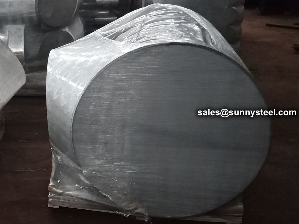
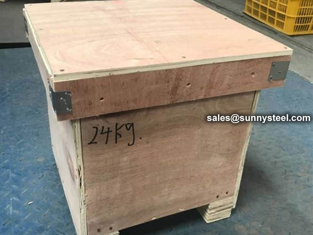
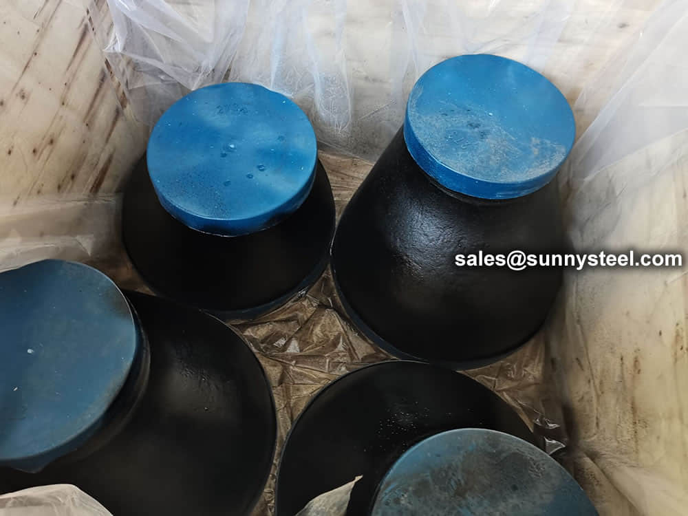 Packing reducers in wooden cases
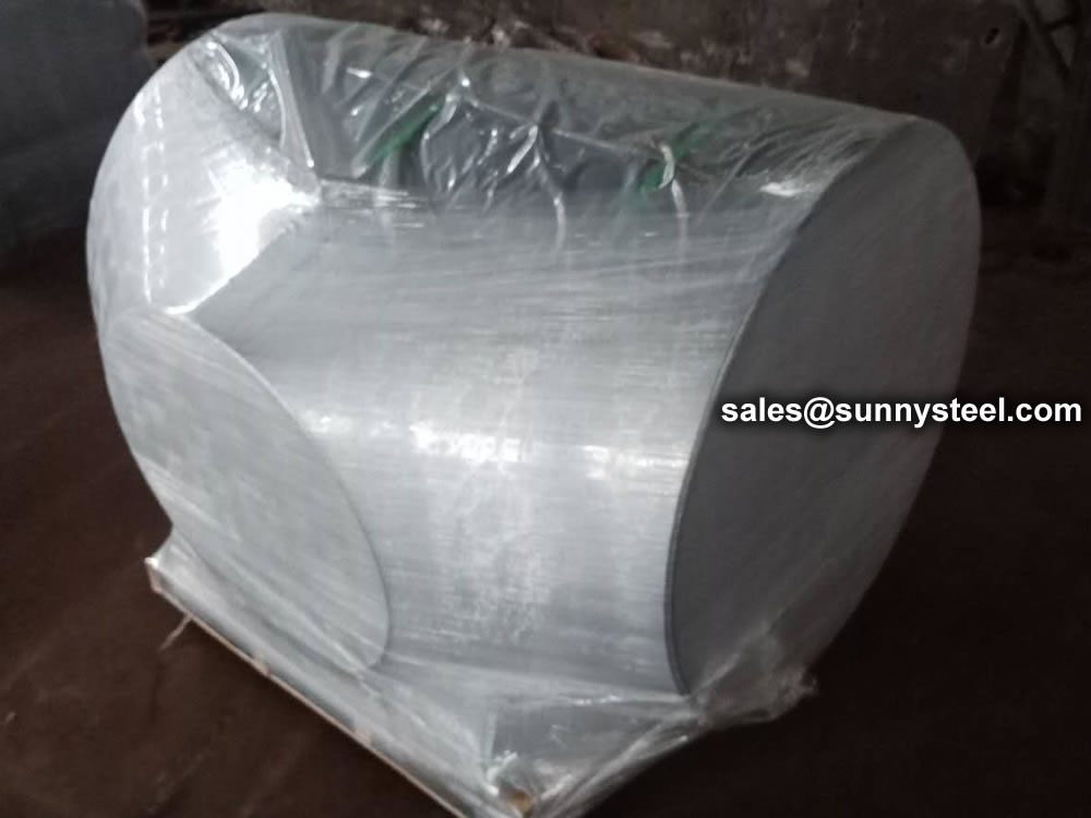
Wrap the plastic tightly around the pipe to protect the tee
Need to inquire about our products? Fill out the form below and our staff will be in touch!
Q: How long is your delivery time? A: The delivery time of customized products is generally 25 35 days, and non customized products are generally shipped within 24 hours after payment. Q: Do you provide samples? Is it free? A: If the value of the sample is low, we will provide it for free, but the freight needs to be paid by the customer. But for some high value samples, we need to charge a fee. Q: What are your payment terms? A: T/T 30% as the deposit,The balance payment is paid in full before shipment Q: What is the packaging and transportation form? A: Non steaming wooden box and iron frame packaging. Special packaging is available according to customer needs. The transportation is mainly by sea. Q: What is your minimum order quantity? A: There is no minimum order quantity requirement. Customized products are tailor made according to the drawings provided by the customer.


