Our team is highly trained and experienced in servicing and producing all types of steel supplies. Need help or have a question?
sales@abrasionresistantpipe.com
Tel.: +8621-3378-0199
Our team is highly trained and experienced in servicing and producing all types of steel supplies. Need help or have a question?
sales@abrasionresistantpipe.com
Tel.: +8621-3378-0199


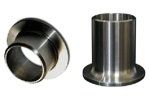
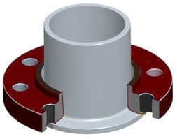
Lap Joint Stub Ends are normally provided with a standard weld bevel. Lap Joint Stub Ends are fittings used in place of welded flanges where rotating back up flanges are desired. A rotating back up flange seats itself against the back surface of the Stub End.
Our high quality stub ends (Butt weld fittings ) are tested and verified for durability, accuracy and precision.
The stub ends are manufactured in all standard dimensions. The stub ends are provided with a standard weld bevel and can be available in squared, flanged, victaulic and threaded ends.
Carbon Steel Stub Ends are manufactured from A106 grade B seamless pipe with Ring and Barrel Construction, per ANSI B16.9 dimensions. The ASTM Fittings Specification is WPB W, welded with no Radiograph of the weld, and they are available in sizes 2″ thru 24″ and in standard and heavy wall thickness.
Seamless stub ends are manufactured from A519/A106 hot rolled seamless to meet ASTM Fitting Specification A234WPB. ASA-A (Long Pattern) stub ends are available in size 1/2″ thru 4″ and in all wall thicknesses. MSS-A (Short Pattern) stub ends are available in sizes 1/2″ thru 6″ and in all wall thicknesses. Type B and Special length threaded stub ends are available upon request.
High quality stub ends (Butt weld fittings ) are tested and verified for durability, accuracy and precision. The stub ends are manufactured in all standard dimensions and provided with a standard weld bevel, it can be available in squared, flanged, victaulic and threaded ends.

| Nominal Pipe Size | 1/2 up to 2.1/2 | 3 to 3.1/2 | 4 |
|---|---|---|---|
| Outside Diameter at Welding End (OD) | 0.8 | 0.8 | 0.8 |
| Overall Length (F) | 1.6 | 1.6 | 1.6 |
| Outside Diameter of Lap (G) | 0 | 0 | 0 |
| -0.76 | -0.76 | -0.76 | |
| Thickness of Lap (T) | 1.52 | 1.52 | 1.52 |
| 0 | 0 | 0 | |
| Fillet Radius of Lap (R) | 0 | 0 | 0 |
| -0.76 | -0.76 | -1.6 | |
| Wall Thickness (t) | Not less than 87.5% of Nominal Wall Thickness |
| Nominal Pipe Size | Outside Diameter at Bevel | Length | Radius of Fillet | Diameter of Lap | |
|---|---|---|---|---|---|
| NPS | OD | L | A | B | D |
| NPS | D | L | R | G | |
| 1/2 | 21.3 | 51 | 3 | 0.8 | 35 |
| 3/4 | 26.7 | 51 | 3 | 0.8 | 43 |
| 1 | 33.4 | 51 | 3 | 0.8 | 51 |
| 1 1/4 | 42.2 | 51 | 5 | 0.8 | 64 |
| 1 1/2 | 48.3 | 51 | 6 | 0.8 | 73 |
| 2 | 60.3 | 64 | 8 | 0.8 | 92 |
| 2 1/2 | 73 | 64 | 8 | 0.8 | 106 |
| 3 | 88.9 | 64 | 10 | 0.8 | 127 |
| 3 1/2 | 101.6 | 76 | 10 | 0.8 | 140 |
| 4 | 114.3 | 76 | 11 | 0.8 | 157 |
| 5 | 141.3 | 76 | 11 | 1.6 | 185 |
| 6 | 168.3 | 89 | 13 | 1.6 | 218 |
| 8 | 219.1 | 102 | 13 | 1.6 | 270 |
| 10 | 273 | 127 | 13 | 1.6 | 324 |
| 12 | 323.8 | 152 | 13 | 1.6 | 381 |
| 14 | 355.6 | 152 | 13 | 1.6 | 413 |
| 16 | 406.4 | 152 | 13 | 1.6 | 470 |
| 18 | 457 | 152 | 13 | 1.6 | 533 |
| 20 | 508 | 152 | 13 | 1.6 | 584 |
| 22 | 559 | 152 | 13 | -- | 641 |
| 24 | 610 | 152 | 13 | 1.6 | 692 |
The Stub End is available with us in different specifications, which find applications in a piping system to allow quick disconnection of the particular section involved.
Stub End is the fitting that be used in place of welded flanges where rotating back up flanges are desired.
MSS Type A stub ends are the industry norm and are utilized with standard flat face lap joint flanges. The lap thickness of the stub end typically meets the thickness of the schedule pipe it accompanies, and the exterior of the base has a curved machine radius for the lap joint flange to mate flush over the stub end. There are many instances in which lead time is critical and of more importance than adherence to existing ANSI / ASME flange specifications, and as such our customers will often choose to purchase a slip on flange and have the face machined to meet the radius requirement of the corresponding stub end piece.
ROC R16.9 2 1/2″ SCH 40S
A403 WPS304L
The MSS standard is the regular length stub end and the most commonly used in the flange industry.

| N.D. | Out diamater | Hight(F) | 翻边直径G | 倒角半径R | ||||
|---|---|---|---|---|---|---|---|---|
| NPS | DN | OD | Mss | ANSI | Nominal&max | Nominal&min | A Max | B Max |
| 1/2 | 15 | 21.3 | 50.8 | 76.2 | 35 | 34 | 3 | 0.8 |
| 3/4 | 20 | 26.7 | 50.8 | 76.2 | 43 | 42 | 3 | 0.8 |
| 1 | 25 | 33.4 | 50.8 | 101.6 | 51 | 50 | 3 | 0.8 |
| 1 1/4 | 32 | 42.4 | 50.8 | 101.6 | 64 | 63 | 4.8 | 0.8 |
| 1 1/2 | 40 | 48.3 | 50.8 | 101.6 | 73 | 72 | 6.4 | 0.8 |
| 2 | 50 | 60.3 | 63.5 | 152.4 | 92 | 91 | 7.9 | 0.8 |
| 2 1/2 | 65 | 73 | 63.5 | 152.4 | 105 | 104 | 7.9 | 0.8 |
| 3 | 80 | 88.9 | 63.5 | 152.4 | 127 | 126 | 9.6 | 0.8 |
| 3 1/2 | 90 | 101.6 | 76.2 | 152.4 | 140 | 139 | 9.6 | 0.8 |
| 4 | 100 | 114.3 | 76.2 | 152.4 | 157 | 156 | 11.2 | 0.8 |
| 5 | 125 | 141.3 | 76.2 | 203.2 | 186 | 185 | 11.2 | 1.6 |
| 6 | 150 | 168.3 | 88.9 | 203.2 | 216 | 215 | 12.7 | 1.6 |
| 8 | 200 | 219.1 | 101.6 | 203.2 | 270 | 269 | 12.7 | 1.6 |
| 10 | 250 | 273.1 | 127 | 254 | 324 | 322 | 12.7 | 1.6 |
| 12 | 300 | 323.9 | 152.4 | 254 | 381 | 379 | 12.7 | 1.6 |
| 14 | 350 | 355.6 | 152.4 | 304.8 | 413 | 411 | 12.7 | 1.6 |
| 16 | 400 | 406.4 | 152.4 | 304.8 | 470 | 468 | 12.7 | 1.6 |
| 18 | 450 | 457.2 | 152.4 | 304.8 | 533 | 531 | 12.7 | 1.6 |
| 20 | 500 | 508 | 152.4 | 304.8 | 584 | 582 | 12.7 | 1.6 |
| 22 | 550 | 559 | 152.4 | 304.8 | 641 | 639 | 12.7 | 1.6 |
| 24 | 600 | 610 | 152.4 | 304.8 | 692 | 690 | 12.7 | 1.6 |
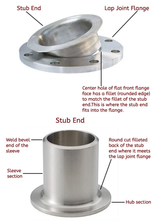
Lap Joint Stub End – The ‘mated’ pair to a Lap Joint Flange. Stub Ends are Fittings used in place of welded flanges where rotating back up flanges are desired. Stub Ends are typically manufactured by two methods, Type A & Type B and are available in two standard lengths , long (ANSI) or short (MSS) pattern.
Features:
Manufacturing standards of stub end:
Specifications:
Lap-joint flanges are most commonly available in carbon steel and low temperature carbon steel, because it is a lower cost than the Stub End that will be wetted by the service and it must be of a suitable grade of steel. If orientation and alignment of bolt holes is the only issue, then for standardization, then the Stub End and the Lap Joint Flange can be of the same material.
The most common material grade for stub end is the ASTM A403 / ASME SA403 (stainless steel stub ends). With reference to EU materials, the most common grades are DIN 1.4301, DIN1.4306, DIN 1.4401, DIN 1.4404.
 Stub Ends assembly
Stub ends and lap joint flanges can be assembled following this process:
It can also be mated to a fabricated plate Flange with compatible, bolting dimensions.

Duplex Stub End and a Duplex Lap Joint, you could have Duplex Stub End and Carbon Steel Lap Flange.
Or you could have Stainless Stub End and Carbon Steel Lap Flange. There are other bimetallic combinations that result in a flange assembly that is commercially cheaper.
During recent years the price differential between Duplex/Stainless Steel and Carbon Steel has narrowed and this practice on large Projects has become less common, however a cost difference always exists (the higher the NPS and the length of the pipeline / piping system, the higher the saving). On the other hand, the warehousing cost of one single component, i.e. a Weld Neck Flange, requires less shelf space than the cost of warehousing a Lap Joint and a Stub End. End Users and Contractors shall determine the actual convenience of using stub ends, considering all these factors and generally the commercial advantage is still valid and it may suit certain situation, especially in “brownfield” modifications.
The following information shall be provided to order a stub end:
Stub ends can be ordered with different ends finishing:
Stub end are offered in three different ways, type A, B and C. Type A and B stub end are similar to forged fittings, such as elbows and tees, and type C stub end are made in customized sizes.
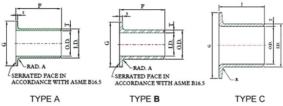
Stub ends are manufactured in three different types and two standard length.
Type “A”: this type is produced and machined to fit lap joint flanges.The mating surfaces of the stub end and the lap joint flange have a matching profile and surface. The lap thickness of type A stub ends is > = the minimum wall thickness of the connected pipe. The outside the stub end and the lap joint flange have a matching profile and surface. The lap thickness of type A stub ends is > = the minimum wall thickness of the connected pipe. The outside corner of type A has a radius to accommodate the lap join flange, whereas the inside corner is squared.
Type “B”: this type of stub ends is suited for standard slip-on flanges acting as lap-joint flanges. The lap thickness of type B stub ends is >= the minimum WT of the connecting pipe. The lap of these type of stub ends has generally a serrated face. To ensure tight joints, chamfers on the ID side of the flange are required.
Type “C”: this last type can be used both with lap joint and slip-on backing flanges and are fabricated out of pipes. The lap of C-type stub ends is flared over and the lap thickness is 75% of the connecting pipe WT. Type C has a short fillet outer radius able to host any back up flange.
Type “CS”: this type is similar to “C” with the difference that the lap face has concentric serrations machined during the manufacturing process.
Common Types and Lengths
Stub ends are usually manufactured in two ways, Type A and Type B. They are available in two standard length, long (ANSI) or short pattern (MSS).
Schedule 5s and 10s stub end are usually offered in short lengths, and long lengths are available on special order. Schedule 40s stub end are supplied in either short or long lengths.
Short pattern (MSS) and long pattern stub ends (ASA)
Stub ends are available in two different patterns:
Dimensions and manufacturing tolerances are covered in ASME B16.9 – Butt Weld Fittings and MSS-SP-43 (JIS B2312, JIS B2313 may also apply).
Stub End come in three standard lengths, MSS SP43 or ANSI B16.9 short and long pattern. Short pattern stub ends are mostly used for flanges from class 300 to class 600 and above. Besides these standard types, End-Users and contractors can require stub ends with non-standard lengths to suit specific project’s requirement. This will of course come at an additional cost.
 Ends/Face lap finishing
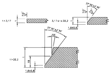
ASME B16.25 END WELDING BEVEL as right
The following types of ends may be ordered:
Beveled Ends (generally ASME B16.25)
Squared Ends
Flanged Ends
Victaulic Grooves
Threaded Ends (Male Only)
| Material | Grade | UNS Equivalent |
|---|---|---|
| A234 WPB Carbon Steel | B | K03006 |
| A403 Stainless Steel | 304/304L | S30403 |
| 304H | S30409 | |
| 316/316L | S31603 | |
| 316H | S31609 | |
| 317L | S31703 | |
| 904L | N08904 | |
| 309S/H | S30908 | |
| 310S | S31008 | |
| 321 | S32100 | |
| 6XN | N08367 | |
| 20CB | N08020 | |
| 347 | S34709 | |
| 254SMO | S31254 | |
| A815 Duplex /Super Duplex | 2205 | S31803/S32205 |
| Zeron 100 | S32760 | |
| 2507 | S32750 | |
| 410 | S41000 | |
| A366 Nickel Alloys | HC22 | N06022 |
| HB-3 | N10675 | |
| HG3 | N06985 | |
| HX | N06002 | |
| HC2000 | N06200 | |
| HC276 | N10276 | |
| NCI | N06600 | |
| NC | N04400 | |
| N | N02200 | |
| NL | N02201 | |
| NCMC | N06625 | |
| NICMC | N08825 | |
| NIC10 | N08810 | |
| NIC11 | N08811 |
Pipe fitting dimensions are in either metric or Standard English. Because pipe fitting covers Pipe Fitting Dimensions several aspects, only the most common pipe fitting sizes can be given here. The most applied version is the 90° long radius and the 45° elbow, while the 90° short radius elbow is applied if there is too little space. The function of a 180° elbow is to change direction of flow through 180°. Both, the LR and the SR types have a center to center dimension double the matching 90° elbows. These fittings will generally be used in furnesses or other heating or cooling units.
Some of the standards that apply to buttwelded fittings are listed below. Many organizations such as ASME, ASTM, ISO, MSS, etc. have very well developed standards and specifications for buttwelded fittings. It is always up to the designer to ensure that they are following the applicable standard and company specification, if available, during the design process.
Some widely used pipe fitting standards are as follows:
ASME: American Society for Mechanical Engineers
This is one of the reputed organizations in the world developing codes and standards.
The schedule number for pipe fitting starts from ASME/ANSI B16. The various classifications of ASME/ANSI B16 standards for different pipe fittings are as follows:
ASTM International: American Society for Testing and Materials
This is one of the largest voluntary standards development organizations in the world. It was originally known as the American Society for Testing and Materials (ASTM).
AWWA: American Water Works Association
AWWA About – Established in 1881, the American Water Works Association is the largest nonprofit, scientific and educational association dedicated to managing and treating water, the world’s most important resource.
ANSI: The American National Standards Institute
ANSI is a private, non-profit organization. Its main function is to administer and coordinate the U.S. voluntary standardization and conformity assessment system. It provides a forum for development of American national standards. ANSI assigns “schedule numbers”. These numbers classify wall thicknesses for different pressure uses.
MSS STANDARDS: Manufacturers Standardization Society
The Manufacturers Standardization Society (MSS) of the Valve and Fittings Industry is a non-profit technical association organized for development and improvement of industry, national and international codes and standards for: Valves, Valve Actuators, Valve Modification, Pipe Fittings, Pipe Hangers, Pipe Supports, Flanges and Associated Seals
Difference between “Standard” and “Codes”:
Piping codes imply the requirements of design, fabrication, use of materials, tests and inspection of various pipe and piping system. It has a limited jurisdiction defined by the code. On the other hand, piping standards imply application design and construction rules and requirements for pipe fittings like adapters, flanges, sleeves, elbows, union, tees, valves etc. Like a code, it also has a limited scope defined by the standard.
Factors affecting standards: “Standards” on pipe fittings are based on certain factors like as follows:
BSP: British Standard Pipe
BSP is the U.K. standard for pipe fittings. This refers to a family of standard screw thread types for interconnecting and sealing pipe ends by mating an external (male) with an internal (female) thread. This has been adopted internationally. It is also known as British Standard Pipe Taper threads (BSPT )or British Standard Pipe Parallel (Straight) threads (BSPP ). While the BSPT achieves pressure tight joints by the threads alone, the BSPP requires a sealing ring.
JIS: Japanese Industrial Standards
This is the Japanese industrial standards or the standards used for industrial activities in Japan for pipe, tube and fittings and published through Japanese Standards Associations.
NPT: National Pipe Thread
National Pipe Thread is a U.S. standard straight (NPS) threads or for tapered (NPT) threads. This is the most popular US standard for pipe fittings. NPT fittings are based on the internal diameter (ID) of the pipe fitting.
BOLTS & NUTS
We are manufacturer of Flange bolts & Nuts and supply high quality
AN: Here, “A” stands for Army and “N” stands for Navy
The AN standard was originally designed for the U.S. Military. Whenever, a pipe fitting is AN fittings, it means that the fittings are measured on the outside diameter of the fittings, that is, in 1/16 inch increments.
For example, an AN 4 fitting means a fitting with an external diameter of approximately 4/16″ or ¼”. It is to be noted that approximation is important because AN external diameter is not a direct fit with an equivalent NPT thread.
Dash (-) size
Dash size is the standard used to refer to the inside diameter of a hose. This indicates the size by a two digit number which represents the relative ID in sixteenths of an inch. This is also used interchangeably with AN fittings. For example, a Dash “8” fitting means an AN 8 fitting.
ISO: International Organization for Standardization
ISO is the industrial pipe, tube and fittings standards and specifications from the International Organization for Standardization. ISO standards are numbered. They have format as follows:
“ISO[/IEC] [IS] nnnnn[:yyyy] Title” where
Pipe fittings are measured by their diameter, wall thickness (known as “schedule”), and shape or configuration. (Fittings are also defined by their material grade and whether they are welded or seamless.)
Diameter refers to outside diameter of a pipe or fitting.
The North American standard is known as Nominal Pipe Size (NPS). The International Standard is known as Diameter Nominal (DN). Pipes and fittings are actually made in similar sizes around the world: they are just labeled differently.
From ½ in to 12 inch “Nominal Pipe Size”, outside diameters are slightly larger than indicated size; inside diameters get smaller as schedules grow.
From 14 in and larger “Nominal Pipe Size”, outside diameters are exactly as indicated size; inside diameters get smaller as schedules grow.
As with other North American standards (inch, foot, yard, mile, …), many pipe standards (diameters up to 12 inch and wall thickness) are based on historical precedents (a toolmaker’s dies during US Civil War) rather than a “scientific” method.
The schedule numbers are used by the ANSI (American National Standards Institute) to denote wall thickness. The schedule numbers encompass all pipe dimensions beginning at NPS 1/8” up NPS 36”. Note that this configuration is only for fittings that match with a particular ANSI schedule number.
Nominal Pipe Size (NPS) is a North American set of standard sizes for pipes used for high or low pressures and temperatures.
What does “schedule” mean for pipe fittings?
Schedule, often shortened as SCH, is a North American standard that refers to wall thickness of a pipe or pipe fitting.
What is schedule 40, SCH80?
Higher schedules mean thicker walls that can resist higher pressures.
Pipe standards define these wall thicknesses: SCH 5, 5S, 10, 10S, 20, 30, 40, 40S, 60, 80, 80S, 100, 120, 140, 160, STD, XS and XXS.
(S following a number is for stainless steel. Sizes without an S are for carbon steel.)
Higher schedules are heavier, require more material and are therefore more costly to make and install.
| Standard | Specification |
|---|---|
| ASTM A234 | Standard Specification for Piping Fittings of Wrought Carbon Steel and Alloy Steel for Moderate and High Temperature Service |
| ASTM A420 | Standard Specification for Piping Fittings of Wrought Carbon Steel and Alloy Steel for Low-Temperature Service |
| ASTM A234 WPB | ASTM A234 is Standard Specification for steel pipe fittings includes carbon and alloy steel material for moderate and high temperature services. WPB is one of the steel grade in this standard |
| ASME B16.9 | ASME B16.9 Standard covers overall dimensions, tolerances,ratings, testing, and markings for factory-made wrought buttwelding fittings in sizes NPS 1⁄2 through NPS 48 (DN 15 through DN 1200). |
| ASME B16.28 | ASME B16.28 Standard covers ratings, overall dimensions, testing, tolerances, and markings for wrought carbon and alloy steel buttwelding short radius elbows and returns. |
| MSS SP-97 | MSS SP-97 Standard Practice covers essential dimensions, finish, tolerances, testing, marking, material, and minimum strength requirements for 90 degree integrally reinforced forged branch outlet fittings of buttwelding, socket welding, and threaded types. |
| ASTM A403 | Standard Specification for Wrought Austenitic Stainless Steel Piping Fittings. |
| DIN | EN | ASME |
|---|---|---|
| St 35.8 I St 35.8 III 15 Mo 3 13 CrMo 4 4 10 CrMo 9 10 St 35 N St 52.0 St 52.4 | P235GH-TC1 P235GH-TC2 16Mo3 13CrMo4-5 10CrMo9-10 X10CrMoVNb9-1 P215NL P265NL L360NB L360NE P355N P355NL1 P355NH | WPB WPL6 WPL3 WPHY 52 WP11 WP22 WP5 WP9 WP91 WP92 |
ASTM A234/ASME SA234M standard specification for piping fittings of wrought carbon steel and alloy steel for moderate and high temperature service.
| Grade | Type | C | Si | S | P | Mn | Cr | Ni | Mo | Other | ób | ós | δ5 |
|---|---|---|---|---|---|---|---|---|---|---|---|---|---|
| WPB | 0.3 | 0.1min | 0.058 | 0.05 | 0.29-1.06 | 0.4 | 0.4 | 0.15 | V:0.06;Nb:0.02 | 415-585 | 240 | 22 | 197 |
| WPC | 0.35 | 0.1min | 0.058 | 0.05 | 0.29-1.06 | 0.4 | 0.4 | 0.15 | V:0.06;Nb:0.02 | 485-655 | 275 | 22 | 197 |
| WP1 | 0.28 | 0.1-0.5 | 0.045 | 0.045 | 0.3-0.9 | 0.44-0.65 | 380-550 | 205 | 22 | 197 | |||
| WP12 CL1 | 0.05-0.2 | 0.6 | 0.045 | 0.045 | 0.3-0.8 | 0.8-1.25 | 0.44-0.65 | 415-585 | 220 | 22 | 197 | ||
| WP12 CL2 | 0.05-0.2 | 0.6 | 0.045 | 0.045 | 0.3-0.8 | 0.8-1.25 | 0.44-0.65 | 485-655 | 275 | 22 | 197 | ||
| WP11 CL1 | 0.05-0.15 | 0.5-1 | 0.03 | 0.03 | 0.3-0.6 | 1-1.5 | 0.44-0.65 | 415-585 | 205 | 22 | 197 | ||
| WP11 CL2 | 0.05-0.2 | 0.5-1 | 0.04 | 0.04 | 0.3-0.8 | 1-1.5 | 0.44-0.65 | 485-655 | 275 | 22 | 197 | ||
| WP11 CL3 | 0.05-0.2 | 0.5-1 | 0.04 | 0.04 | 0.3-0.8 | 1-1.5 | 0.44-0.65 | 520-690 | 310 | 22 | 197 | ||
| WP22 CL1 | 0.05-0.15 | 0.5 | 0.04 | 0.04 | 0.3-0.6 | 1.9-2.6 | 0.87-1.13 | 415-585 | 205 | 22 | 197 | ||
| WP22 CL3 | 0.05-0.15 | 0.5 | 0.04 | 0.04 | 0.3-0.6 | 1.9-2.6 | 0.87-1.13 | 520-690 | 310 | 22 | 197 | ||
| WP5 CL1 | 0.15 | 0.5 | 0.03 | 0.04 | 0.3-0.6 | 4-6 | 0.44-0.65 | 415-585 | 205 | 22 | 217 | ||
| WP5 CL3 | 0.15 | 0.5 | 0.03 | 0.04 | 0.3-0.6 | 4-6 | 0.44-0.65 | 520-690 | 310 | 22 | 217 | ||
| WP9 CL1 | 0.15 | 1 | 0.03 | 0.03 | 0.3-0.6 | 8-10 | 0.9-1.1 | 415-585 | 205 | 22 | 217 | ||
| WP9 CL3 | 0.15 | 1 | 0.03 | 0.03 | 0.3-0.6 | 8-10 | 0.9-1.1 | 520-690 | 310 | 22 | 217 | ||
| WPR | 0.2 | 0.05 | 0.045 | 0.4-1.06 | 1.6-2.24 | 435-605 | 315 | 22/28 | 217 | ||||
| WP91 | 0.08-0.12 | 0.2-0.5 | 0.01 | 0.02 | 0.3-0.6 | 8-9.5 | 0.4 | 0.85-1.05 | See sdandard | 585-760 | 415 | 20 | 248 |
| WP911 | 0.09-0.13 | 0.1-0.5 | 0.01 | 0.02 | 0.3-0.6 | 8.5-10.5 | 0.4 | 0.9-1.1 | See sdandard | 620-840 | 440 | 20 | 248 |
| Tensile Requirements | WPB | WPC, WP11CL2 | WP11CL1 | WP11CL3 |
|---|---|---|---|---|
| Tensile Strength, min, ksi[MPa] (0.2% offset or 0.5% extension-under-load) | 60-85 [415-585] | 70-95 [485-655] | 60-85 [415-585] | 75-100 [520-690] |
| Yield Strength, min, ksi[MPa] | 32 [240] | 40 [275] | 30 [205] | 45 [310] |
ASTM A403 Standard specification covers the standard for wrought austenitic stainless steel fittings for pressure piping applications.
| Steel No. | Type | C | Si | S | P | Mn | Cr | Ni | Mo | Other | ób | ós | δ5 |
|---|---|---|---|---|---|---|---|---|---|---|---|---|---|
| WP304 | 0.08 | 1 | 0.03 | 0.045 | 2 | 18-20 | 8-11 | 515 | 205 | 28 | |||
| WP304H | 0.04-0.1 | 1 | 0.03 | 0.045 | 2 | 18-20 | 8-11 | 515 | 205 | 28 | |||
| WP304L | 0.035 | 1 | 0.03 | 0.045 | 2 | 18-20 | 8-13 | 485 | 170 | 28 | |||
| WP304LN | 0.03 | 0.75 | 0.03 | 0.045 | 2 | 18-20 | 8-10.5 | N2:0.1-0.16 | 515 | 205 | 28 | ||
| WP304N | 0.08 | 0.75 | 0.03 | 0.045 | 2 | 18-20 | 8-11 | N2:0.1-0.16 | 550 | 240 | 28 | ||
| WP309 | 0.15 | 1 | 0.03 | 0.045 | 2 | 22-24 | 12-15 | 515 | 205 | 28 | |||
| WP310 | 0.15 | 1.5 | 0.03 | 0.045 | 2 | 24-26 | 19-22 | 515 | 205 | 28 | |||
| WP316 | 0.08 | 1 | 0.03 | 0.045 | 2 | 16-18 | 10-14 | 2-3 | 515 | 205 | 28 | ||
| WP316H | 0.04-0.1 | 1 | 0.03 | 0.045 | 2 | 16-18 | 10-14 | 2-3 | 515 | 205 | 28 | ||
| WP316LN | 0.03 | 0.75 | 0.03 | 0.045 | 2 | 16-18 | 11-14 | 2-3 | N2:0.1-0.16 | 515 | 205 | 28 | |
| WP316L | 0.035 | 1 | 0.03 | 0.045 | 2 | 16-18 | 10-16 | 2-3 | 485 | 170 | 28 | ||
| WP316N | 0.08 | 0.75 | 0.03 | 0.045 | 2 | 16-18 | 11-14 | 2-3 | N2:0.1-0.16 | 550 | 240 | 28 | |
| WP317 | 0.08 | 1 | 0.03 | 0.045 | 2 | 18-20 | 11-15 | 3-4 | 515 | 205 | 28 | ||
| WP317L | 0.03 | 1 | 0.03 | 0.045 | 2 | 18-20 | 11-15 | 3-4 | 515 | 205 | 28 | ||
| WP321 | 0.08 | 1 | 0.03 | 0.045 | 2 | 17-20 | 9-13 | Ti:5C-0.7 | 515 | 205 | 28 | ||
| WP321H | 0.04-0.1 | 1 | 0.03 | 0.045 | 2 | 17-20 | 9-13 | Ti:4C-0.7 | 515 | 205 | 28 | ||
| WP347 | 0.08 | 1 | 0.03 | 0.045 | 2 | 17-20 | 9-13 | Nb+Ta:10C-1.1 | 515 | 205 | 28 | ||
| WP347H | 0.04-0.1 | 1 | 0.03 | 0.045 | 2 | 17-20 | 9-13 | Nb+Ta:8C-1 | 515 | 205 | 28 | ||
| WP348 | 0.08 | 1 | 0.03 | 0.045 | 2 | 17-20 | 9-13 | Ta:0.1 | 515 | 205 | 28 | ||
| WP348H | 0.04-0.1 | 1 | 0.03 | 0.045 | 2 | 17-20 | 9-13 | Ta:0.1 | 515 | 205 | 28 |
| Grade | UNS | Tensile Strength, min | Yield Strength,min | Elongation min % in 4D | |||
|---|---|---|---|---|---|---|---|
| ksi | MPa | ksi | MPa | Longit % | Trans% | ||
| ALL | ALL | 75 | 515 | 30 | 205 | 28 | 20 |
| 304L | S30403 | 70 | 485 | 25 | 170 | 28 | 20 |
| 316L | S31603 | 70 | 485 | 25 | 170 | 28 | 20 |
| 304N | S30451 | 80 | 550 | 35 | 240 | 28 | 20 |
| 316N | S31651 | 80 | 550 | 35 | 240 | 28 | 20 |
| S31726 | 80 | 550 | 35 | 240 | 28 | 20 | |
| XM-19 | S20910 | 100 | 690 | 55 | 380 | 28 | 20 |
| S31254 | 94-119 | 650-820 | 44 | 300 | 28 | 20 | |
| S34565 | 115 | 795 | 60 | 415 | 28 | 20 | |
| S33228 | 73 | 500 | 27 | 185 | 28 | 20 | |
Material Furnished to this specification shall conform to the requirements of specifications A960/A960M including any supplementary requirements that are indicates in the purchase order. Failure to company with the common requirements of Specification A960/A960M constitutes non-conformance with this specification . In case of conflict between this specification and Specification A960/A960M , this specification shall prevail.
ASTM A420/A420M-07 standard specification for piping fittings of wrought carbon steel and alloy steel for low-temperature service.
| Elements | WPL6, % | WPL9, % | WPL3, % | WPL8, % |
|---|---|---|---|---|
| Carbon [C] | ≤0.30 | ≤0.20 | ≤0.20 | ≤0.13 |
| Manganese [Mn] | 0.50-1.35 | 0.40-1.06 | 0.31-0.64 | ≤0.90 |
| Phosphorus [P] | ≤0.035 | ≤0.030 | ≤0.05 | ≤0.030 |
| Sulfur [S] | ≤0.040 | ≤0.030 | ≤0.05 | ≤0.030 |
| Silicon [Si] | 0.15-0.40 | … | 0.13-0.37 | 0.13-0.37 |
| Nickel [Ni] | ≤0.40 | 1.60-2.24 | 3.2-3.8 | 8.4-9.6 |
| Chromium [Cr] | ≤0.30 | ... | ... | ... |
| Molybdenum [Mo] | ≤0.12 | ... | ... | ... |
| Copper [Cu] | ≤0.40 | 0.75-1.25 | … | … |
| Columbium [Cb] | ≤0.02 | ... | ... | ... |
| Vanadium[V] | ≤0.08 | ... | ... | ... |
| ASTM A420/ A420M | Tensile Strength, min. | Yield Strength, min. | Elongation %, min | |||
|---|---|---|---|---|---|---|
| Grade | ksi | MPa | ksi | MPa | Longitudinal | Transverse |
| WPL6 | 65-95 | 415-655 | 35 | 240 | 22 | 12 |
| WPL9 | 63-88 | 435-610 | 46 | 315 | 20 | … |
| WPL3 | 65-90 | 450-620 | 35 | 240 | 22 | 14 |
| WPL8 | 100-125 | 690-865 | 75 | 515 | 16 | … |
ASTM A234 is Standard Specification for steel pipe fittings includes carbon and alloy steel material for moderate and high temperature services.
ASME B16.9 Standard covers overall dimensions, tolerances,ratings, testing, and markings for factory-made wrought buttwelding fittings in sizes NPS 1⁄2 through NPS 48 (DN 15 through DN 1200).
| Nominal | Outside Diameter | 90° Elbows | 45° Elbows | 180° Returns | ||||
|---|---|---|---|---|---|---|---|---|
| Pipe Size | Long Radius | Short Radius | Long Radius | Long Radius | ||||
| (inches) | (mm) | (inches) | Center to Face | Center to Face | Center to Face | Radius | Center to Center | Back to face |
| (inches) | (inches) | (inches) | (inches) | (inches) | (inches) | |||
| 1/2 | 21.3 | 0.84 | 1.5 | – | 5/8 | 2 | 1.875 | |
| 3/4 | 26.7 | 1.05 | 1.125 | – | 7/16 | 2.25 | 1.6875 | |
| 1 | 33.4 | 1.315 | 1.5 | 1 | 7/8 | 3 | 2.1875 | |
| 1.25 | 42.2 | 1.66 | 1.875 | 1.25 | 1 | 3.75 | 2.75 | |
| 1.5 | 48.3 | 1.9 | 2.25 | 1.5 | 1.125 | 3 | 4.5 | 3.25 |
| 2 | 60.3 | 2.375 | 3 | 2 | 1.375 | 4 | 6 | 4.1875 |
| 2.5 | 73 | 2.875 | 3.75 | 2.5 | 1.75 | 5 | 7.5 | 5.1875 |
| 3 | 88.9 | 3.5 | 4.5 | 3 | 2 | 6 | 9 | 6.25 |
| 3.5 | 101.6 | 4 | 5.25 | 3.5 | 2.25 | 7 | 10.5 | 7.25 |
| 4 | 114.3 | 4.5 | 6 | 4 | 2.5 | 8 | 12 | 8.25 |
| 5 | 141.3 | 5.563 | 7.5 | 5 | 3.125 | 10 | 15 | 10.3125 |
| 6 | 168.3 | 6.625 | 9 | 6 | 3.75 | 12 | 18 | 12.3125 |
| 8 | 219.1 | 8.625 | 12 | 8 | 5 | 12 | 24 | 16.3125 |
| 10 | 273.1 | 10.75 | 15 | 10 | 6.25 | 15 | 30 | 20.375 |
| 12 | 323.9 | 12.75 | 18 | 12 | 7.5 | 18 | 36 | 24.375 |
| NOMINAL PIPE SIZE NPS | ANGULARITY TOLERANCES | ANGULARITY TOLERANCES |
|---|---|---|
| Size | Off Angle Q | Off Plane P |
| ½ to 4 | 0.03 | 0.06 |
| 5 to 8 | 0.06 | 0.12 |
| 10 to 12 | 0.09 | 0.19 |
| 14 to 16 | 0.09 | 0.25 |
| 18 to 24 | 0.12 | 0.38 |
| 26 to 30 | 0.19 | 0.38 |
| 32 to 42 | 0.19 | 0.5 |
| 44 to 48 | 0.18 | 0.75 |
MSS SP-97 Standard Practice covers essential dimensions, finish, tolerances, testing, marking, material, and minimum strength requirements for 90 degree integrally reinforced forged branch outlet fittings of buttwelding, socket welding, and threaded types.
| Nominal wall Thickness : t | End Preparation |
|---|---|
| t<5mm (for austenitic alloy steel t<4mm) | Cut square or slightly chamfer at manufacturer ‘ s option |
5| Plain Bevel as in sketch ( a ) above |
|
| t>22mm | Compound Bevel as in sketch ( b ) above |
| Elements | Value, % |
|---|---|
| Carbon (C) | ≤0.30 |
| Manganese (Mn) | ≤1.60 |
| Phosphorus (P) | ≤0.035 |
| Sulfur (S) | ≤0.035 |
| Copper (Cu) | ≤0.50 |
| Nickel (Ni) | ≤0.50 |
| Silicon (Si) | ≤0.50 |
| Chromium (Cr) | ≤0.25 |
| Molybdenum (Mo) | ≤0.13 |
| Vanadium (V) | ≤0.13 |
| Columbium (Cb) | ≤0.10 |
| Titanium(Ti) | ≤0.05 |
 The use of stub ends has these two advantages:
Reduces the overall cost of the flanged joint Generally, the lap joint flange is of a lower grade than the material of the stub end and the pipework, thus saving the total weight of high-grade material used for the flanged joint.
Reduces the overall cost of the flanged joint
Generally, the lap joint flange is of a lower grade than the material of the stub end and the pipework, thus saving the total weight of high-grade material used for the flanged joint.
Example:
For an SS316 pipe, instead of using a full 316 welding neck flange, a combination of an SS316 stub end and a carbon steel lap joint flange would do the same exact job, but the total weight of SS316 material would be lower, and the cost as well.
Essentially, stub ends allow to minimize the weight of high-grade material in stainless, duplex, and nickel alloy piping, saving costs. Of course, the bigger the diameter and the class of the flanges, the higher the saving!
Commercial advantages are that the Stub End, will be wetted and it must be made of a grade of material that meets the process design and service conditions of the pipeline. However, the Lap Flange is un-wetted and it can be made of a lower grade of material as long as it meets
the mechanical strength requirements of the piping systems.
The “loose” Flange concept of a Lap Joint, is very beneficial during field installation of piping systems. If two spools are to be mated up in the field, having one Flange that can be rotated is very advantageous when aligning the bolt holes, prior to the introduction of the Stub bolt and the accompanying nuts. The facility of easier orientation and alignment of bolt holes, is of particular use it there is a spool that
has to be removed frequently, if positive isolation is a process requirement.
A Lap Joint consists of two independent components that are not integrated with a weld and like for like in size/pressure class/material it lacks the mechanical strength and capabilities to withstand fatigue, like a one piece Weld Neck Flange or a welded together Slip On or Socket Weld Flanges. In cyclic services, collars EN 1092-1 type 35 PN 16-25-40 are used instead of stub ends (especially to close pumps and compressors). If carefully consideration is given to Process Design condition, the service and the final application, then a Lap Joint Flange mechanical connection are a valid and cheaper method for installing piping systems compared to the use of standard flanges.
A stud end and a lap joint flange can be used together as an alternative way to make a flanged connection than welding neck flanges.
 Stub end is widely used in the petroleum, chemical, power, gas, metallurgy, shipbuilding and construction industries. It is made from high quality raw materials, and available in a variety of sizes and designs. The combination of stub ends and backing flanges is an alternative way to join pipes compared to the use of standard flanges.
90° Lateral Wye R500 DN150 Export to Pilipinas with lap-joint flanges
This solution is used in these typical scenarios:
Why use Stub Ends?
A stud end and a lap joint flange can be used together as an alternative way to make a flanged connection than welding neck flanges.
The two devices to be combined, in this case, are:
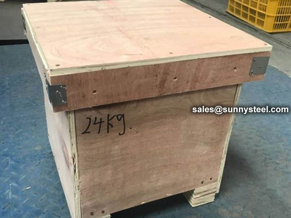
For packing of carbon steel flanges with painting,we would use the bubble wrap to protect the painting.For flanges without painting or oiled with long-term shipment,we would suggest client to use the anti-tarnish paper and plastic bag to prevent the rust. 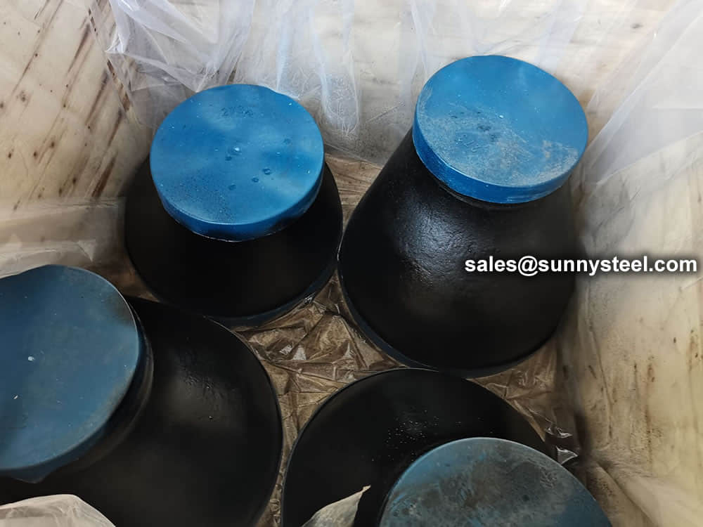 Packing reducers in wooden cases
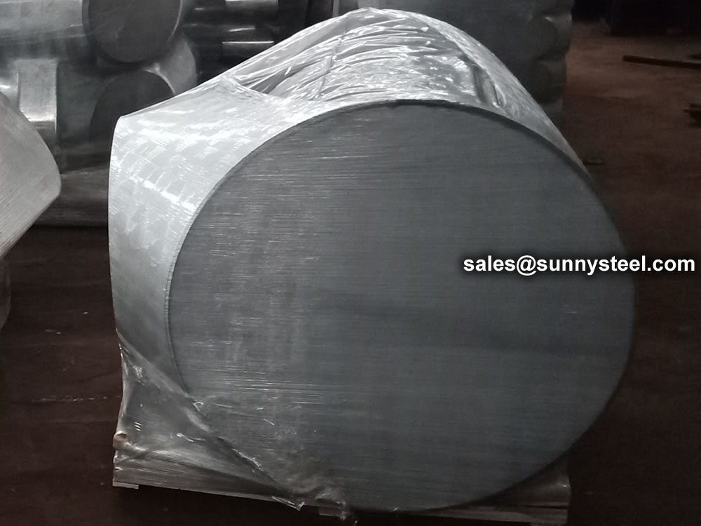
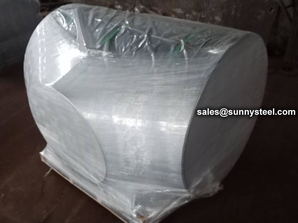
Wrap the plastic tightly around the pipe to protect the tee
Need to inquire about our products? Fill out the form below and our staff will be in touch!
Q: How long is your delivery time? A: The delivery time of customized products is generally 25 35 days, and non customized products are generally shipped within 24 hours after payment. Q: Do you provide samples? Is it free? A: If the value of the sample is low, we will provide it for free, but the freight needs to be paid by the customer. But for some high value samples, we need to charge a fee. Q: What are your payment terms? A: T/T 30% as the deposit,The balance payment is paid in full before shipment Q: What is the packaging and transportation form? A: Non steaming wooden box and iron frame packaging. Special packaging is available according to customer needs. The transportation is mainly by sea. Q: What is your minimum order quantity? A: There is no minimum order quantity requirement. Customized products are tailor made according to the drawings provided by the customer.


