Our team is highly trained and experienced in servicing and producing all types of steel supplies. Need help or have a question?
sales@abrasionresistantpipe.com
Tel.: +8621-3378-0199
Our team is highly trained and experienced in servicing and producing all types of steel supplies. Need help or have a question?
sales@abrasionresistantpipe.com
Tel.: +8621-3378-0199


Heat exchanger tubes are intended for heating or cooling process fluids, they are for example suitable for closed circuit cooling of electrical equipment using demineralised water and for cooling water soluble oil solutions in quenching tanks.
Heat exchange tubes are intended for heating or cooling process fluids, they are for example suitable for closed circuit cooling of electrical equipment using demineralised water and for cooling water soluble oil solutions in quenching tanks.
Heat exchange tubes used for heat transfer usually use primary cold-drawn heat exchange tubes and ordinary cold-drawn heat exchange tubes. The former is suitable for heat transfer and vibration occasions without phase change, and the latter is suitable for reboiling, condensing heat transfer and vibration-free general occasions. The heat exchanger pipe shall be able to withstand certain temperature differences, stress and corrosion resistance. The length of the heat exchange tube is generally 1.0m, 1.5m, 2.0m, 2.5m, 3.0m, 4.5m, 6.0m, 7.5m, 9.0m, 12.0m. The material of the pipe can be carbon steel, stainless steel, aluminum, copper, brass and copper-nickel alloy, nickel, graphite, glass and other special materials, also often used composite pipe. In order to expand the area of effective heat transfer tube at the same time maximize the tube side heat transfer coefficient, heat exchange tube processing or in tube inserted into the internal and external surfaces of the disturbed flow components, producing fluid turbulence the inside and outside at the same time, commonly used such as rough surface tubes, finned tube, the supporting pipe, inside the plug-in type, etc.
Heat exchanger Tubes are used in all types of process industries. Characteristic requirements are: bead worked weld, fixed lengths and extensive testing. In order to meet the demand for rapid delivery, we have a strip stock with both standard and special grades of steel in the most common thicknesses.
We supply both seamless and welded tubes which meet the requirements for shell and tube heat exchangers:
Size range 6.35mm – 76.2mm OD x 0.91mm – 3.25mm wall thickness
Heat exchanger tubes are supplied in Standard Wire Gauge (SWG) or Birmingham Wire Gauge (BWG)
Popular grades: 1.4306 (304L), 1.4404 (316L)
Whether your application requires seamless or welded stainless steel tubing, you can always count on consistent, high quality tubing manufactured by our specialists at Sunny Steel. Many of the world’s leading heat exchanger manufacturer’s turn to us for their tubing needs.
Applications include:
We offer quick turnaround as well as specialty and nickel alloys.
Delivery Conditions:
Mechanical Test
Surface treatment:
Shell-and-tube designs incorporate fixed or floating tubesheets, fixed or removable tube bundles and expansion joints as needed to create an effective heat transfer vessel. Gain a better understanding of the TEMA types to improve your selection process.

These heat exchangers are in the final stages of fabrication.
Among the most common types of heat transfer equipment used in industrial applications are the various configurations of shell-and-tube heat exchangers. Suitable for a range of pressure and temperature conditions, shell-and-tube heat exchangers can be robust enough to handle corrosive or even lethal fluids.
The shell-and-tube heat exchanger design allows heat transfer between two independent, pressurized chambers through the walls of the tubes. The design consists of an array of tubes, which is connected on each side to a flat plate called a tubesheet. The tubesheet also separates the shell and tube sides of the exchanger. Baffles on the outside of the tubes direct the flow of the shell-side fluid back and forth across the tubes to promote heat transfer. The process fluid can flow through either the shell or tube side, with the opposite side typically acting as the service side (usually a heating or cooling medium). The exchanger also can have a process fluid on both sides.
For most shell-and-tube heat exchanger types, the first step in designing an exchanger for a specific process is thermal design. Given the process conditions and heat transfer requirements, the thermal design determines the exchanger’s size, shape, number and size of tubes, number of baffles and baffle pitch, etc. Other factors considered at this stage include allowable pressure drop through the exchanger, any space constraints on the unit, the potential fouling of the unit and any resulting flow-induced vibration from the proposed design.
After the exchanger size is determined by the thermal design, a mechanical design is performed. This step determines the thickness of all parts as well as welding details required for the temperature and pressure conditions.
Many different configurations of shell-and-tube heat exchangers are available. There are advantages and disadvantages to each design, depending on factors such as process and thermal requirements, available space, financial budget and cleaning requirements. This article provides information on several of the most widely used configurations and briefly discusses some of the issues to consider when planning for and selecting a heat exchanger configuration.
The Tubular Exchanger Manufacturers Association, or TEMA, publishes a standard that establishes design, fabrication, tolerances, installation and maintenance of shell-and-tube type exchangers. This standard and the ASME code are the main standards used to design and fabricate exchangers along with any applicable customer specifications. The TEMA standard also defines the classes and main configuration styles of exchangers.

Removable bundle exchangers give the customer the ability to replace the tube bundle without replacing the shell or Bonnets. They are generally less cost effective than non removable designs.
BEU/AEU– U Bundle Exchangers are generally the most cost effective design style of removable bundle exchanger. Tubes may be water blasted, steam or chemically cleaned. These units must have an even number of tube passes, sometimes limiting their applicability to a service(e.g. they generally can not be used when a temperature cross occurs).
CEU– This design has the tubesheet welded to the Bonnet. You can remove the bundle from the shell, however to replace the bundle, the inlet Bonnet is included or you must cut off the tubesheet. Tubes may be chemically cleaned, water blasted or steam cleaned.
BEW/AEW– These are straight tube units with one floating head and one stationary head. The floating head is generally sealed with an O-Ring. These units are most often used as oil coolers or air coolers. Cleaning can be performed by either a chemical, mechanical method, water blast or steam cleaning.
AEP/BEP– These are straight tube units with one inside packed floating head and one stationary head. The floating head is generally sealed with packing. These units are most often used as intercoolers and aftercoolers with the gas on the tube side. They are also the most common style for oxygen service exchangers. These units have been used in services with tube side design pressures in excess of 2000 PSIG.
TEMA, Tubular Exchanger Manufacturers Association
AES/AET- These units are the most expensive of the removable bundle designed units. The floating head is internal to the shell. Tubes can be cleaned mechanically , chemically, water blasted or steam cleaned. The design of these units forces an even number of tube side passes therefore they suffer the same service restrictions as U bundles. Although in theory one pass unit can be designed, this is rarely done. These units are generally used in services where U bundles are not desired and the service may be too corrosive/damaging to the packing used in AEP/BEP units.

These types of units are often used in high pressure services and services where you wish to avoid leakage problems at gasketed joints. Another advantage is that they are generally more cost effective than removable bundle designs.
NEU- The most cost effective design available. The tubesheet is welded to both the shell and Bonnet. There is no access to the shell. Tubes may be chemically cleaned, water blasted or steam cleaned from inside only. These units are commonly used in high pressure services (such as feedwater heaters), where process conditions allow for even pass exchangers.
NEN- Tubesheets are welded to both the Shell and Bonnets. Access to the tubes is through covers on the channels. These units are favored in very high pressure designs as their construction minimizes the tubesheet thickness and number of high pressure retaining flanges.
AEM/BEM/AEL-SHELL side is completely welded up, however, the Bonnets are removable. Chemical, mechanical, and water blast cleaning of the tubes is possible, however you do not have access to the shell.
You should avoid using Steam cleaning on a fixed tube sheet unit unless the unit has a shell side expansion joint. The steam will cause the tubes to expand and pull out of the Tube Sheet causing failure at startup.
 How is the heat exchange tube connected with the tube sheet?
The connection form of heat exchange tube and tube plate mainly includes expansion, welding, expansion welding, etc. The strength expansion joint refers to the expansion of the sealing performance and tensile strength of the connection between the heat exchange tube and the tubesheet. It relies on the plastic deformation of the tube end to withstand the pulling force. The residual stress after the expansion of the tube will gradually weaken when the temperature increase so that the sealing performance and strength of the connection between the tube and the tube sheet will decrease.
Therefore, the strength expansion is suitable for the design pressure is less than or equal to 4MPa, the design temperature is less than or equal to 300℃. The strength expansion should not be used in the case of severe vibration, large temperature difference, or obvious stress corrosion during operation.
When expanding the tube, the hardness of the tube should be lower than that of the tube sheet. The gap between the pipe and the pipe and the smoothness of the pipe affects the quality of the expanding pipe. The rough surface of the pipe hole can produce a large friction force and is not easy to pull off, but it is easy to produce leakage. The surface of the pipe hole is strictly prohibited to have a longitudinal through the groove. The smooth surface of the tube hole is not easy to leak, but easy to pull off. Generally, the surface roughness is required to be less than or equal to 12.5μm. There are two kinds of pipe holes: holes and annular grooving, the former as shown in figure (a) below, and the latter as shown in Figure (b) and (c) below.
After grooving, the steel tubes are squeezed into the grooves when expanding, which can improve the pull-off resistance and enhance the sealing performance. The number of annular slots in the tube hole depends on the thickness of the tube plate. Generally speaking, a slot is opened when the thickness is less than 25mm, and two slots are opened when the thickness is greater than 25mm. When the tube plate is thick or to avoid gap corrosion, the structure shown in the following figure (d) can be used, the composite tube plate and heat exchange tube can also be expanded, when the cladding is greater than or equal to 8mm, should be in the groove on the tube hole, the structure is shown in the following figure (e).
Strength welding refers to ensure the sealing performance and tensile strength of the heat exchange tube and tubesheet connection, is the most widely used tubesheet connection types. Strength welding manufacturing is simple, the tensile ability is strong, such as welding part failure, can be secondary repair welding, more convenient heat exchange tube. The use of strength welding is not limited by pressure and temperature, but it is not suitable for the occasion of large vibration or gap corrosion. The general form of strength welding is shown in figure (a) below. In order to avoid liquid accumulation around the pipe end, the structure as shown in figure (b) below is often used. The structure as shown in figure (c) below is generally used in the situation where the tubesheet is stainless steel.

The sealing performance of the joint between tube and tube plate is required to be high, or there is clearance corrosion, withstand severe vibration and other occasions, single expansion or welding can not meet the requirements, the combination of the two can provide enough strength and good sealing performance. The combination of expansion and welding can be divided into two kinds according to the expansion and welding sequence: expansion and welding after expansion. The general expansion method will inevitably have oil stains in the joint gap, which will be welded after expansion. These oil stains and the air in the gap will reduce the weld quality.
Weld before expansion, will cause damage to the weld. At present, there is no uniform provision for the choice of the two orders. In the actual engineering, such as expansion after welding, before welding should be clean oil; If the first welding after expansion, should be a limit to the expansion position of the tube end, generally to control from the surface of the tube plate 15mm above the scope of expansion. The first expansion and then welding generally adopts the form of strength expansion and seal welding. The strength expansion ensures the sealing performance of the tube and tubesheet, providing enough tensile strength, and the seal welding further ensures the sealing performance of the tube and tubesheet. The structure is shown in the figure (a). Strength welding ensures the sealing performance of the tube and tubesheet, providing sufficient tensile strength, and sticking expansion eliminate the gap between the tube and the tube hole to ensure the sealing performance. The structure is shown in figure (b).
In essence, explosive expansion is also a kind of strength expansion, the latter usually adopts roller expansion, the former uses the explosive in a very short period of time to produce high-pressure gas shock wave to make the pipe firmly attached to the tube hole. High explosive expansion and connection efficiency, no need of lubricating oil, easy to weld after expansion, large tensile strength, small axial elongation and deformation.
Explosive expansion is suitable for thin wall tubes, small diameter tubes and large thickness tube sheet expansion, heat exchange tube end leakage, mechanical expansion is difficult to repair the occasion.
 Advantages of U tube heat exchanger
U tube heat exchanger is characterized by its simple structure, good tightness, convenient maintenance and cleaning, low cost, good thermal compensation performance and strong pressure bearing capacity. The U-tube heat exchanger has the largest heat exchange area under the same diameter. The main structure of U-shaped tube heat exchanger includes tube box, cylinder, head, heat exchange tube, nozzles, baffle, anti-shock plate and guide tube, anti-short circuit structure, support and other accessories of the shell and tube side, is the most commonly used in shell and tube heat exchanger.
Tube sheet
Tube sheet is one of the most important parts of shell – tube heat exchanger. The tube plate is the barrier between the shell side and the pipe side. When the heat exchange medium has no corrosion or slight corrosion, it is generally made of low carbon steel, low alloy steel or stainless steel. The connection form of tube-sheet and shell is divided into non-detachable and detachable types. The former is the connection between tube-sheet and shell in the fixed tube-sheet heat exchanger. The latter, such as U-shaped tube type, floating head type and stuffing box type and sliding tube plate type heat exchanger tube plate and shell connection. For removable connections, the tube plate itself is usually not in direct contact with the shell, but the flange is connected to the shell indirectly or is clamped by two flanges on the shell and the tube box.
Tube box
Most of the shell tube heat exchangers with larger shell diameters adopt tube and box structures. The tube box is located at both ends of the heat exchanger, which evenly distributes the fluid from the pipe to the heat exchanger tubes and gathers the fluid in the tubes together to send out the heat exchanger. In a multi-pipe shell, the casing can also change the flow direction. The structure of the tube box is mainly determined by whether the heat exchanger needs to be cleaned or whether the tube bundle needs to be divided.
Shell and U-tube heat exchanger has become the most commonly used structure type of heat exchanger in the field of petrochemical industry due to many advantages, but it also has some disadvantages such as pipe cleaning is more difficult, the utilization rate of tube plate is low due to the limitation of curvature radius of bend pipe; The distance between the innermost tubes of the tube bundle is large, the shell process is easy to short circuit, and the scrap rate is high. It is suitable for large temperature difference between pipe and shell wall or shell side where medium is easy to scale and needs cleaning, and is not suitable for using floating and fixed tube plate type occasions, especially suitable for clean and not easy to scale under high temperature, high pressure, corrosive medium.
 What is a tube sheet ( tubesheet ) in heat exchanger ?
A tube sheet is usually made from a round flat piece of plate,sheet with holes drilled to accept the tubes or pipes in a accurate location and pattern relative to one another.The tube sheets are used to support and isolate tubes in heat exchangers and boilers or to support filter elements. Tubes are attached to the tube sheet by hydraulic pressure or by roller expansion. A tube sheet may be covered in a cladding material which serves as a corrosion barrier and insulator. Low carbon steel tube sheets can include a layer of a higher alloy metal bonded to the surface to provide more effective corrosion resistance without the expense of using the solid alloy,which means it can save a lot of cost.
Tube sheet is one of the most important parts of shell – tube heat exchanger. The tube plate is the barrier between the shell side and the pipe side. When the heat exchange medium has no corrosion or slight corrosion, it is generally made of low carbon steel, low alloy steel or stainless steel. The connection form of tube-sheet and shell is divided into non-detachable and detachable types. The former is the connection between tube-sheet and shell in the fixed tube-sheet heat exchanger. The latter, such as U-shaped tube type, floating head type and stuffing box type and sliding tube plate type heat exchanger tube plate and shell connection. For removable connections, the tube plate itself is usually not in direct contact with the shell, but the flange is connected to the shell indirectly or is clamped by two flanges on the shell and the tube box.
Perhaps the best known use of tube sheets are as supporting elements in heat exchangers and boilers. These devices consist of a dense arrangement of thin walled tubes situated inside an enclosed, tubular shell. Tubes are supported on either end by sheets which are drilled in a predetermined pattern to allow the tube ends to pass through the sheet. The ends of the tubes which penetrate the tube sheet are expanded to lock them in place and form a seal. The tube hole pattern or “pitch” varies the distance from one tube to the other and angle of the tubes relative to each other and to the direction of flow. This allows the manipulation of fluid velocities and pressure drop, and provides the maximum amount of turbulence and tube surface contact for effective Heat Transfer.
In cases where it is critical to avoid fluid intermixing, a double tube sheet can be provided. The design of tube sheets is a fairly precise and complex process; the exact number of tubes needs to be established and a pattern of holes calculated to spreads them evenly over the tube sheet surface. Large exchangers may have several thousand tubes running through them arranged into precisely calculated groups or bundles. Sheet design and production is largely automated these days with computer software (like CAD) performing the calculations and the tube sheet drilling done on computer numerical control (CNC) machines. In this design, the outer tube sheet is outside the shell circuit, virtually eliminating the chance of fluid intermixing. The inner tube sheet is vented to atmosphere so any fluid leak is easily detected. Duwa Piping factory drilling department has professional drilling equipment and working team, we can provide the best quality tube sheet for you.
| Abbr. | Corresponding | Application |
|---|---|---|
| A179 | ASTM A179 / A179M | Standard Specification for Seamless Cold-Drawn Low-Carbon Steel Heat-Exchanger and Condenser Tubes |
| A213 | ASTM A213/A213M | Specification for Seamless Ferritic and Austenitic Alloy-Steel Boiler, Superheater, and Heat-Exchanger Tubes |
| A214 | ASTM A214 / A214M | Specification for Electric-Resistance-Welded Carbon Steel Heat-Exchanger and Condenser Tubes |
| A249 | ASTM A249 / A249M | Specification for Welded Austenitic Steel Boiler, Superheater, Heat-Exchanger, and Condenser Tubes |
| A498 | ASTM A498 / A498M | Specification for Seamless and Welded Carbon, Ferritic, and Austenitic Alloy Steel Heat-Exchanger Tubes with Integral Fins |
| A851 | ASTM A851 / ASME SA851 | Specification for High-Frequency Induction Welded, Unannealed, Austenitic Steel Condenser Tubes |
The production of our seamless pipes is tightly regulated and all of the pipes we stock have been fully tested to international standards to ensure we only supply the highest quality products.
| Product name | Executive standard | Dimension (mm) | Steel code/ Steel grade |
|---|---|---|---|
| Black and Hot-dipped Zinc-coated Steel Pipes Seamless | ASTM A53 | 0.3-1200 x 1.0-150 | GR.A, GR.B, GR.C |
| Seamless Carbon Steel for High Temperature Service | ASTM A106 | 10.3-1200 x 1.0-150 | GR.B, GR.C |
| Seamless Cold-drawn Low-Carbon Steel Heat-Exchanger and Condenser Tubes | ASTM A179 | 10.3-426 x 1.0-36 | Low Carbon Steel |
| Seamless Carbon Steel Boiler Tubes for High Pressure | ASTM A192 | 10.3-426 x 1.0-36 | Low Carbon Steel |
| Seamless Cold-drawn Intermediate Alloy Steel Heat-exchanger and Condenser Tubes | ASTM A199 | 10.3-426 x 1.0-36 | T5, T22 |
| Seamless Medium-carbon Steel Boiler and Superheater Tubes | ASTM A210 | 10.3-426 x 1.0-36 | A1, C |
| Seamless Ferritic and Austenitic Alloy Steel Boiler, Superheater and Heat-exchanger Tubes | ASTM A213 | 10.3-426 x 1.0-36 | T5, T5b, T9 , T11, T22 ,T91 |
| Seamless Carbon and Alloy Steel for Mechanical Tubing | ASTM A333 | 1/4"-42" x SCH20-XXS | Grade1 Gr. 3,Gr..6, Gr.8 , Gr. 9 |
| Seamless Cold-drawn Carbon Steel Feedwater Heater Tubes | ASTM A556 | 10.3-426 x 1.0-36 | A2, B2 |
| Round and shaped steel cold formed welded and seamless carbon steel structural pipe. | ASTM A500 | OD :10.3-820 x 0.8- 75 | Grade A, B, C, D |
| Carbon and alloy steel mechanical tubing, either hot-finished or cold-finished | ASTM A519 | 10.3-426 x 1.0-36 | 1020, 1025, 4130, 4140 |
| For seamless ferritic alloy-steel pipe for high-temperature service | ASTM A335 | 1/4"-42" x SCH20-XXS | A/SA 335 P1, P2, P11, P12, P15, P22, P91, P92, P122 |
Cold Drawn Seamless Mechanical Tubing (CDS) is a cold drawn 1018/1026 steel tube which offers uniform tolerances, enhanced machinability and increased strength and tolerances compared to hot-rolled products. 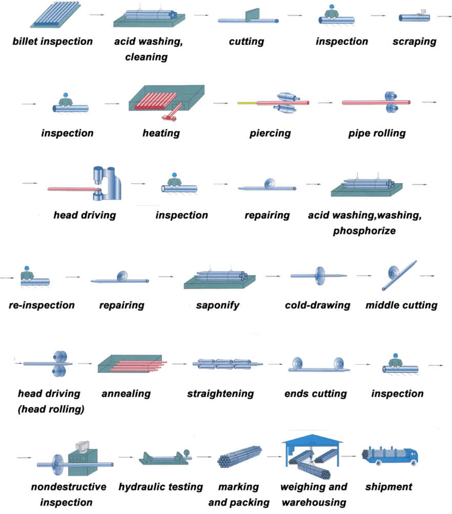 Cold drawn steel tube is with hot-rolled steel coil as raw material, and tandem cold rolling pickled to remove oxide scale, its finished rolling hard roll, rolling hard volumes due to the continuous cold deformation caused by cold hardening strength, hardness increased indicators declined tough plastic, stamping performance will deteriorate, which can only be used for simple deformation of the parts. Rolling hard roll can be used as the raw material of the hot-dip galvanizing plant, hot dip galvanizing line set annealing line. Rolling hard roll weight is generally 6 to 13.5 tons, the coil diameter of 610mm.
Hot-rolled seamless steel pipe production base deformation process can be summarized as three stages: perforation, extension and finishing. 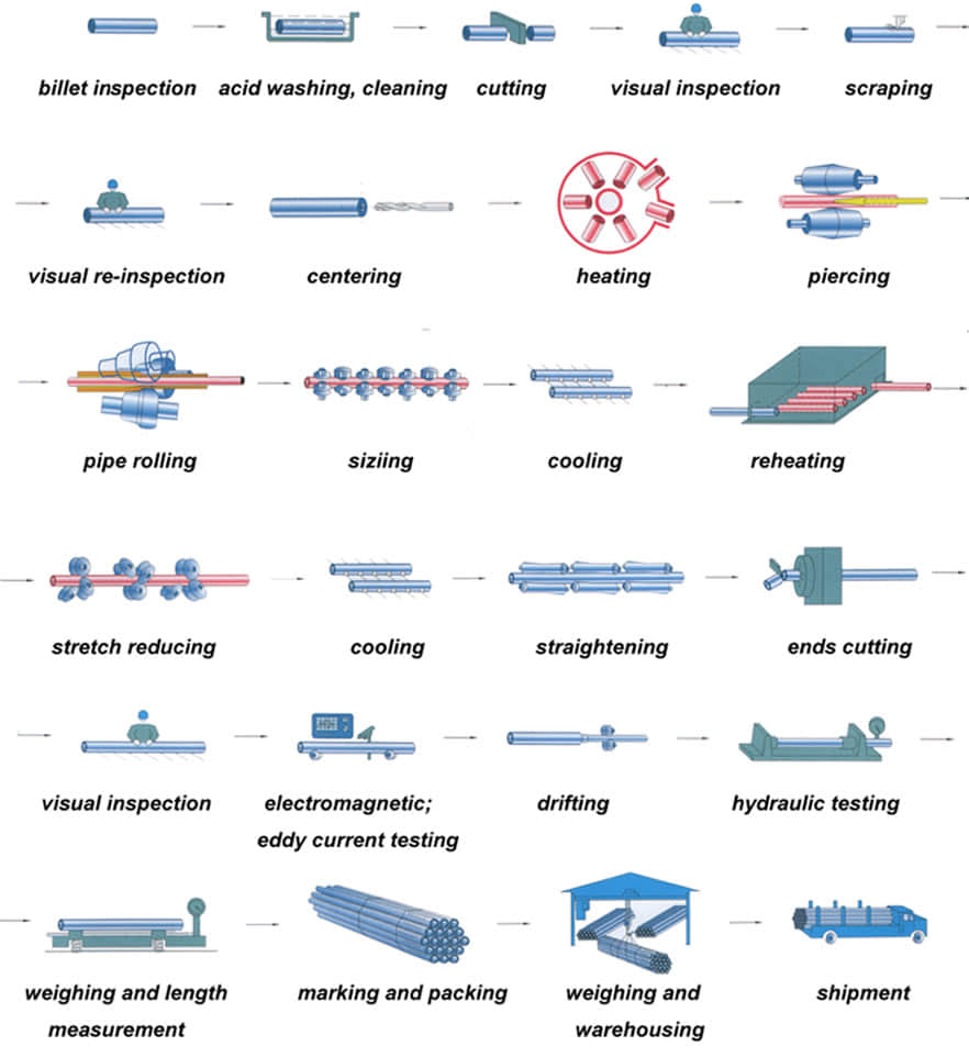 The main purpose of the perforation process is to become a solid round billet piercing hollow shell. Capillary in the specifications, accuracy and surface quality can not meet the requirements of the finished product, further improvements are needed to deform the metal through. The main purpose of the stretching machine is further reduced sectional view (main compression wall) for a larger axial extension, so that the capillary improved dimensional accuracy, surface quality and organizational performance. After stretching machine rolled steel pipe shortage collectively need further molding mill in order to achieve the requirements of the finished pipe. Rolled steel due to pass in the method widely used in the production of seamless steel tubes. So far, due to the method pass rolling steel can be divided into two categories: core pension without rolling rolling (hollow body rolling), and with the mandrel. Sizing machines, reducing mill and stretch reducing mill belonging to the hole without mandrel type continuous rolling mills are generally coffin. Its main purpose is to reduce the diameter of the deformation process or sizing get finished steel, the wall thickness of process control, can make thinning, thickening or nearly unchanged. All the traditional hole-type rolling machine with mandrel belong to extend machine. The main purpose is to reduce the deformation process perforated capillary wall thickness and outer diameter roll passes in the deformation zone and the mandrel posed, for a larger axial extension. At the same time a certain improvement in the organization, performance, accuracy, surface quality.
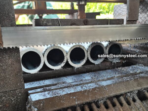
Before cutting pipe and tubing No matter the material, measure the diameter of the pipe or tube to be cut to ensure that you use the right-size tube cutter for the job. When determining how to make a straight cut, use a tape measure and a pencil or other writing instrument to mark on the surface where you want to cut. If possible, mark around the circumference of a pipe, especially when cutting with a handsaw. Ensure that a cut is as straight as possible by securing the pipe with a vise, clamp, miter box or even duct tape to keep the length from shifting out of place while cutting. After cutting pipe and tubing
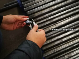
Geometrical inspection of steel pipes The outer diameter, wall thickness, bending and length of the steel pipe can be inspected on the inspection table with an outer caliper, a micrometer and a bending ruler, and a length tape measure.
Take seamless steel pipe as an example, there are some tolerances that affect quality. Noting this, and you will get a better pipe.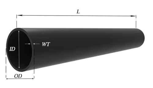
Weight tolerance
For pipe NPS 12 (DN300, 323.8mm) and under, the weight shall vary within -3.5% / +10%.
For pipe over NPS 12 (DN300, 323.8mm), the weight shall vary within -5% / +10%.
Pipe of NPS 4 (DN100, 114.3mm) and smaller may be weighed in convenient lots; pipe in sizes larger than NPS 4 shall be weighed separately.
Quantity tolerance
Normally mills take -10% to +10% tolerance, but TPMCSTEEL keeps ±3% variation.
Length tolerance
For Seamless pipe& tube, if definite cut lengths are ordered, the length shall vary within -0mm / +6mm.
| Pipe types | Pipe Szie(mm) | Tolerances | |
|---|---|---|---|
| Hot rolled | OD | <50 | ±0.50mm |
| ≥50 | ±1% | ||
| WT | <4 | ±12.5% | |
| ≥4-20 | +15%, -12.5% | ||
| >20 | ±12.5% | ||
| Cold drawn | OD | 6-10 | ±0.20mm |
| 10-30 | ±0.40mm | ||
| 30-50 | ±0.45 | ||
| >50 | ±1% | ||
| WT | <1 | ±0.15mm | |
| >1-3 | + 15%, – 10% | ||
| >3 | + 12.5%, – 10% | ||
| Standard | Hot finished seamless tube | Cold flnished seamless tube | ||
|---|---|---|---|---|
| Out diameter (mm) | Tolerance | Out diameter (mm) | Tolerance | |
| EN10216-1 | ≤100 | +/-0.75% (min.+/-0.5mm) | All | +/-0.5% |
| EN10216-2 | (min. +/-0.30mm) | |||
| DIN17175 | >100 | +/-0.90% | ||
| GB/T 3087 | ≤460 | +/-0.75% (min.+/-0.5mm) | 10-30 | +/-0.40mm |
| >30-50 | +/-0.45mm | |||
| >50 | +/-1.0% | |||
| GB/T 5310 GB/T 9948 GB/T 6479 | <57 | +/-0.40mm | ≤30 | +/-0.20mm |
| 57-325 | +/-0.75% | >30-50 | +/-0.30mm | |
| >325-460 | +1%,-2mm | >50 | +/-0.8% | |
| ASME SA-179M ASME SA-192M ASME SA-209M ASME SA-210M ASME SA-213M JIS G 3461 JIS G 3461 | ≤101.6 | +0.4, -0.8mm | <25.4 | +/-0.10mm |
| >25.4-38.1 | +/-0.15mm | |||
| >38.1-50.8 | +/-0.20mm | |||
| 101.6-190.5 | +0.4, -1.2mm | >50.8-63.5 | +/-0.25mm | |
| >63.5-76.2 | +/-0.30mm | |||
| >76.2 | +/-0.38mm | |||
| ASME SA106 ASME SA335 | ≤48.3 | +/-0.40mm | ≤48.3 | +/-0.40mm |
| 48.3-114.3 | +/-0.79mm | |||
| 114.4-219.1 | +1.59, -0.79mm | |||
| 219.2-323.9 | +2.38, -0.79mm | >48.3 | +/-0.79mm | |
| >324 | +/-1.0% | |||
| Standard | Hot finished seamless tube | Cold flnished seamless tube | ||||
|---|---|---|---|---|---|---|
| DIN17175 | Out diameter OD(mm) | Wall thickness T(mm) | Tolerance | Out diameter (mm) | Wall Thickness T(mm) | Tolerance |
| ≤130 | S≤2Sn | +15%, -10% | -- | All | +/-10% (min. +/-0.2mm) |
|
2Sn| +12.5%, -10% |
| |||||
| S>4Sn | +-/9% | |||||
| >130 | S≤0.05da | +17.5%, -12.5% | ||||
0.05da| +/-12.5% |
| |||||
| S>0.11da | +/-10% | |||||
| EN 10216-1 EN 10216-2 | ≤219.1 | - | +/-12.5% (min.+/-0.4mm) |
|||
| -- | T/D≤0.025 | +/-20% | ||||
0.025| +/-15% |
| |||||
0.05| +/-12.5% |
| |||||
0.1| +/-10% |
| |||||
| GB/T 3087 | -- | ≤20 | +15%,-12.5% (min.+0.45, -0.35mm) | -- | 1.0-3.0 | +15%, -10% |
| >20 | +/-12.5% | -- | >3 | +12.5%, -10% | ||
| GB/T 5310 GB/T 9948 GB/T 6479 | -- | <4.0 | +15%,-10% (min.+0.48, -0.32mm) | -- | 2-3 | +12%,-10% |
| 4-20 | +12.5%,-10% | >3 | +/-10% | |||
| >20 | +/-10% | |||||
| ASME SA-179M ASME SA-192M ASME SA-209M ASME SA-210M ASME SA-231M JIS G 3461 JIS G 3462 | -- | 2.41-3.8 | +35%, -0% | ≤38.1 | -- | +20%,-0% |
| 3.8-4.6 | +33%,-0% | >38.1 | -- | 22%,-0% | ||
| >4.6 | +28%,-0% | -- | -- | -- | ||
| ASME SA-106 ASME SA-335 | -- | All | +/12.5% | All | +/-10% | |
Note:

Positive material identification (PMI) testing is the examination of a material, usually a metallic alloy, to confirm the material is consistent with the user’s request.
Steel pipe delivery status(condition): cold / hard (BK), cold / soft (BKW), after cold stress relief annealing (BKS), annealing (GBK), normalized (NBK).
| Term | Symbol | Explanation |
|---|---|---|
| Cold-finished/hard (cold-finished as-drawn) | BK | No heat treatment after the last cold-forming process. The tubes therefore have only low deformability. |
| Cold-finished/soft (lightly cold-worked) | BKW | After the last heat treatment there is a light finishing pass (cold drawing) With proper subsequent processing, the tube can be cold-formed (e.g. bent, expanded) within certain limits. |
| Annealed | GBK | After the final cold-forming process the tubes are annealed in a controlled atmosphere or under vacuum. |
| Normalized | NBK | The tubes are annealed above the upper transformation point in a controlled atmosphere or under vacuum. |
There are probably hundreds of different methods for packing a pipe, and most of them have merit, but there are two principles that are vital for any method to work prevent rusting and Sea transportation security. 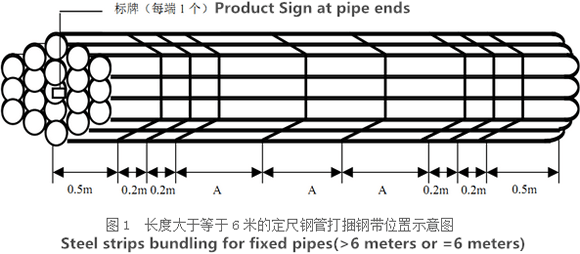
Our packing can meet any needs of the customers.
Need to inquire about our products? Fill out the form below and our staff will be in touch!
Q: How long is your delivery time? A: The delivery time of customized products is generally 25 35 days, and non customized products are generally shipped within 24 hours after payment. Q: Do you provide samples? Is it free? A: If the value of the sample is low, we will provide it for free, but the freight needs to be paid by the customer. But for some high value samples, we need to charge a fee. Q: What are your payment terms? A: T/T 30% as the deposit,The balance payment is paid in full before shipment Q: What is the packaging and transportation form? A: Non steaming wooden box and iron frame packaging. Special packaging is available according to customer needs. The transportation is mainly by sea. Q: What is your minimum order quantity? A: There is no minimum order quantity requirement. Customized products are tailor made according to the drawings provided by the customer.


