Our team is highly trained and experienced in servicing and producing all types of steel supplies. Need help or have a question?
sales@abrasionresistantpipe.com
Tel.: +8621-3378-0199
Our team is highly trained and experienced in servicing and producing all types of steel supplies. Need help or have a question?
sales@abrasionresistantpipe.com
Tel.: +8621-3378-0199


The weldoflange and nipo flange is a combination of a welding neck flange and a supposedly weldolet or nipolet. Nipoflange is a connection that has a flange on one side and a Nipolet on the other side. This allows for welding with the pipe with the Nipolet and then a regular flange connection on the other end.
The weldoflange and nipo flange is a combination of a welding neck flange and a supposedly weldolet or nipolet.
On the run pipe side a nipoflange is designed like a weldolet. That means the branch connection on the run pipe side is a welding connection. On the other side there it has a flange connection. The flange connection can be designed according to customers requirements (acc. To DIN or ANSI).
A nipoflange similar to ANSI B 16.9 or MSS-SP 97 is manufactured from forged material. That means a nipoflange is a forged fitting without welding seam.
Of course, you may obtain a standard cert. 3.1 with each delivery. Upon request, we are able to deliver a cert 3.2 (normally TüV or other inspection institutions). In the cert. 3.1, the chemical consistenc and the physical characteristics of the material are listed.
Standard and special materials
Anthermo is able to deliver nipoflanges in standard materials. Upon request special materials are also deliverable.
The Weldoflange and Nipoflange is a combination of a Welding Neck flange and a supposedly Weldolet or Nipolet. The 2 components are manufactured in one piece, and not welded. These flanges are primarily in Branch connections. Furthermore, they have an expanded range of special flanges, fittings and branch connections.

Nipoflange is a connection that has a flange on one side and a Nipolet on the other side. This allows for welding with the pipe with the Nipolet and then a regular flange connection on the other end. Stainless Steel Nipoflange Dimensions mandate the range of NPS 26 through NPS 60 up to 60 inches. A Carbon Steel Nipo Flange is used on a branch connection. Where corrosion resistance and ligh weight are preferred, the Alloy Steel Nipo Flange is used. Class 150 Nipoflange is a low pressure class flange. The different alloys such as the Inconel Nipoflange and the Hastelloy Nipo Flanges can serve different properties and purposes.


They can remain original in up to 870 degrees Celsius; meaning, they can withstand high temperatures without losing the strength and corrosion resistance properties. There are many makes such as the Reinforced Nipoflange which is a nickel alloy flange. They are used in many other industries such as the sea water cooling systems, wiring components in electrostatic precipitators, oil refineries acetic acid industry, architectural structures such as railings and many more. The mechanical properties of these flanges make them oxidation resistant.The different compositions are used to match with the differently alloyed pipelines and to match the strength and pressure requirements of the applications.
A combination of weldneck flange and nipolet is a nipoflange. Nipoflange is shaped like a nipolet on the run side and has a flange connection on the branch size.
 Flange-Olet
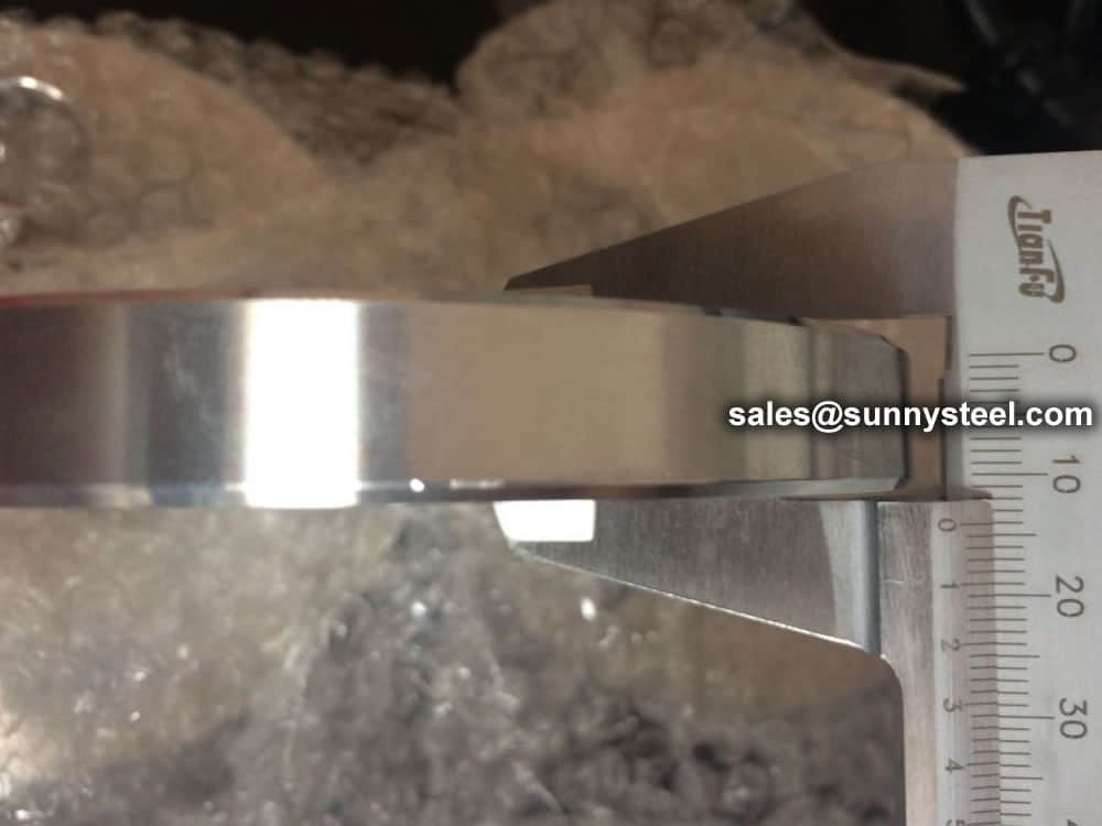
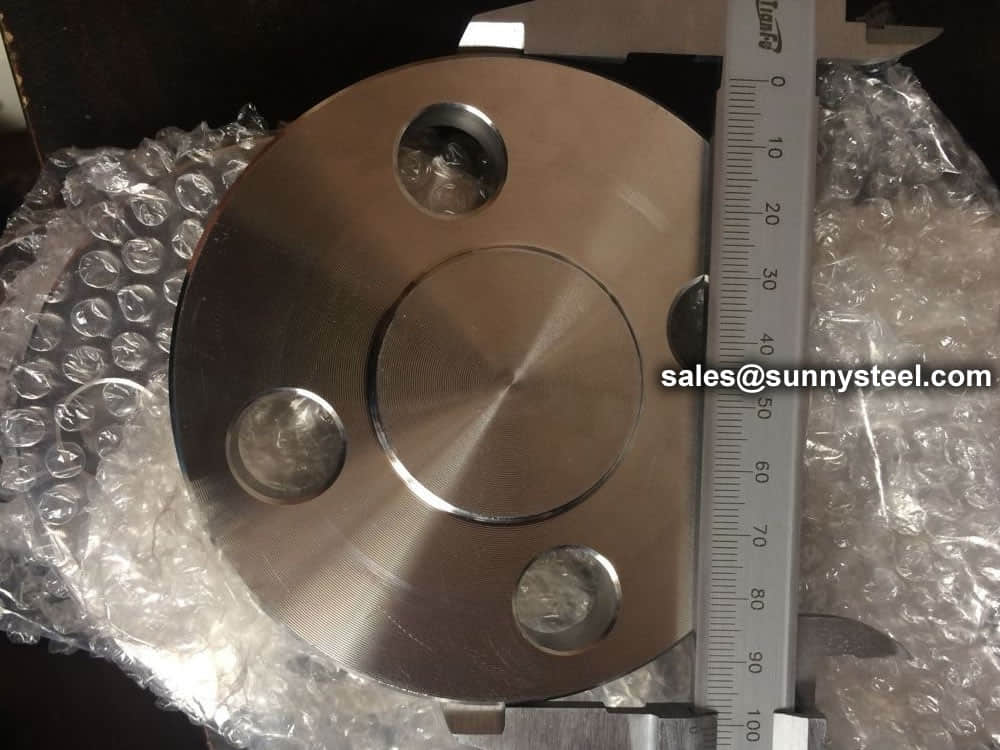
A flange-olet (flange-outlet) is also called nipoflange or weldoflange,its shape looks like a Long weld neck flange.It could be regarded as a combination of a long weld neck flange and a weldolet,or a nipolet welded with a weld neck flange.
The flange-olet is used for a 90° branch connection from a main pipe.On the run pipe side,the flangeolet is designed like a weldolet,it will welded with the run pipe as a branch of the pipe.On another side,the flange-olet is a flange connection,this flange dimensions could be designed as per EN1092,ASME/ANSI B16.5 standard or other codes.
The flange-olet is produced in forging and machining process,it is forged material,commonly the flange-olet is a integral forging without any welding seam.It is first produced in forging process from UK.The flange-olet could be in forged carbon steel material,stainless steel material or alloy steel material.
| Types | Description |
|---|---|
| Blind Flange | These flanges do not have a bore. It is used to blind off a flange or even a valve. When used at the end of a pipe or fitting, it provides an easy to open access for further extension of the pipe. The blind flange and its bolts are stressed more than any other flange. |
| Lap Joint Flange | This flange is used with a lap joint stub end fitting. It is similar to a slip-on flange, but with two differences. The radius and the flat face, both allow the flange to secure against the stub end fitting. This is useful where alignment of bolt holes is difficult, such as with spools to be attached to flanged nozzles of vessels. A lap joint is used in low pressure applications and not suitable where high external of heavy loads are present. |
| Slip-on Flange | Slip-on flanges are designed to slip over the outside of pipe, long-tangent elbows, reducers, and swages. The flange has poor resistance to shock and vibration. It is easier to align than a weld neck flange. This flange is ideal for low pressure applications since the strength when under internal pressure is about one third that of a weld neck flange. |
| Socket Weld Flange | This is similar to a slip-on flange, except they have a bored and counter bore. The counter bore allows the pipe to fit into the socket/counter bore. The bore of the flange is the same diameter as the inside of the pipe. These flanges were first designed for small diameter, high pressure pipe. |
| Threaded Flange | It is similar to a slip-on Flange, but has internal threads. It is normally used for low pressure and not used where temperature or stress is very high. |
| Weld Neck Flange | This flange comes in two types, regular and long. The hub of the weld neck is designed to reduce the stress at the base of the flange. Regular weld neck flanges are used with buttweld fittings and long weld neck flanges are usually used with equipment and vessel nozzles. A long weld neck flange is rarely used with pipe. Both types of flanges are bored to match the inside diameter of the pipe or fitting to which it will be welded to. They are suitable where high pressure, extreme temperatures, shear impact and vibratory stresses apply. |
| Types | Description |
|---|---|
| Spectacle blind flange | A spectacle flange is a specialty flange made of two metal discs attached in the middle by a small section of steel. Spectable flanges get their name because they look like a pair of reading glasses, or spectacles. |
| Reducing Flange | Reducing flanges are designed for when there is a change in the pipe size. |
| Orifice Flange | Orifice flanges are for metering the volumetric flow rate of liquids and gasses through a pipe. This flange is normally available in weld neck, slip-on, and threaded flanges. |
| Weldoflange / Nipoflange | A weldoflange is an olet connection, it is simular to a nipoflange, both are used for a branch connection on a pipe. |
| Expander Flange | An expander flange is similar to a weld neck flange but with the hub expanding to a larger size (one or two sizes). |
| Custom flanges | Our experts are exceptional at machining custom flanges for life. We have experience helping engineers, estimators, purchasing agents and more with their custom flanges. |
| Anchor flange | An anchor flange is a device to restrain pipe movement in a piping system,it looks like a weld neck flange but has two hubs on the both sides to weld with the pipes,but there is no bolt bores on the anchor flanges. |
| Standard Connection Flange | This flange is normally used for nozzles on pressure vessels and rarely used with pipe. |
The most common way of classifying flanges is by considering their shapes. However, it’s essential to understand that there are other ways to categorize flanges, as these come in handy when durability, functionality, and application are in question. These include:
Remember the types of flanges described in the beginning of this article? (Welding Neck, Slip-On, Threaded, Socket Weld, Lap-Joint and Blind), well those were the standard types, now you’ll see that the types of flanges available in the type of the flange is very similar to them, so all the “pros” and “cons” described there can be applied here.
The types divided the flanges in three groups: loose, integral and optional. Below I’ll describe these types according to the Code.
Loose Type Flanges:
This type covers those designs in which the flange has no direct connection to the nozzle neck, vessel, or pipe wall, and designs where the method of attachment is not considered to give the mechanical strength equivalent of integral attachment.
Integral Type Flanges:
This type covers designs where the flange is cast or forged integrally with the nozzle neck, vessel or pipe wall, butt welded thereto, or attached by other forms of arc or gas welding of such a nature that the flange and nozzle neck, vessel or pipe wall is considered to be the equivalent of an integral structure. In welded construction, the nozzle neck, vessel, or pipe wall is considered to act as a hub.
Optional Type Flanges:
This type covers designs where the attachment of the flange to the nozzle neck, vessel or pipe wall is such that the assembly is considered to act as a unit, which shall be calculated as an integral flange, except that for simplicity the designer may calculate the construction as a loose type flange provided none of the following values is exceeded: g0 = 5/8″ (16 mm), B/g0 = 300, P = 300 psi (2 MPa) and operating temperature = 700°F (370°C).
Pipe Flange Standards mainly include three systems in the world, ANSI/ASME flange system(American), DIN flange system(European system), JIS flange system, other system made according to this three systems, like GB flange standard, which mainly made according to ANSI/ASME and DIN flange standard, Duwa Piping supplies those flanges with top quality and soonest delivery time.
ASME B16.1 – Gray Iron Pipe Flanges and Flanged Fittings: Classes 25, 125, and 250
ASME B16.5 – Pipe Flanges and Flanged Fittings: NPS 1/2 through NPS 24 Metric/Inch Standard
ASME B16.20 – Ring Joint Gaskets and Grooves for Steel Pipe Flanges
ASME B16.21 – Nonmetallic Flat Gaskets for Pipe Flanges
ASME B16.24 – Cast Copper Alloy Pipe Flanges and Flanged Fittings: Classes 150, 300, 600, 900, 1500, and 2500
ASME B16.34 – Large Diameter Steel Flanges (NPS 26 through NPS 60)
ASME B16.36 – Orifice Flanges
ASME B16.42 – Ductile Iron Pipe Flanges and Flanged Fittings: Classes 150 and 300
ASME B16.47 – Large Diameter Steel Flanges (NPS 26 Through NPS 60)
ASTM A105 – Specification for Carbon Steel Forgings for Piping Applications
ASTM A182 – Specification for Forged or Rolled Alloy Steel Pipe Flanges, Forged Fittings, and Valves and Parts for High Temperature Service
ASTM A193 – Specification for Alloy Steel and Stainless Steel Bolting Materials for High Temperature Service
ASTM A194 – Specification for Carbon and Alloy Steel Nuts for Bolts for High Pressure and High Temperature Service
ASTM A694 – Specification for Carbon and Alloy Steel Forgings for Pipe Flanges, Fittings, Valves, and Parts for High-Pressure Transmission Service
ASTM A707 – Specification for Flanges, Forged, Carbon and Allow Steel for Low Temperature Service
AWWA C115 – Standard for Flanged Ductile Iron Pipe with Ductile-Iron or Gray-Iron Threaded Flanges
ISO 5251 – Stainless steel butt-welding fittings
MSS SP-6 – Standard Finishes for Contact Faces Pipe Flanges and Connecting End Flanges of Valves and Fittings
MSS SP-9 – Spot Facing for Bronze, Iron and Steel Flanges
MSS SP-25 – Standard Marking Systems for Valves, Fittings, Flanges, and Unions
MSS SP-44 – Steel Pipeline Flanges
MSS SP-53 – Quality Standards for Steel Castings and Forgings for Valves, Flanges and Fittings and Other Piping Components – Magnetic Particle
MSS SP-54 – Quality Standards for Steel Castings and for Valves, Flanges and Fittings and Other Piping Components – Radiographic
MSS SP-55 – Quality Standards for Steel Castings and for Valves, Flanges and Fittings and Other Piping Components – Visual
MSS SP-75 – High Test Wrought Butt Welding Fittings
MSS SP-106 – Cast Copper Alloy Flanges and Flanged Fittings Class 125,150, and 300
ASME B16.5 and ASME B16.47 cover pipe flanges up to NPS 60 (B16.5 from 1/2″ to 24″ and B16.47 from 26″ to 60″). ANSI B16.47 covers two series of flanges, Series A is equal to MSS SP-44-44, and Series B is equal to API 605 (API 605 has been canclled).
Only the most used flange classes are listed on this page. For more information on flanges and their respective standards, please follow the link below.
The concept of flange ratings likes clearly. A Class 300 flange can handle more pressure than a Class 150 flange, because a Class 300 flange are constructed with more metal and can withstand more pressure. However, there are a number of factors that can impact the pressure capability of a flange.
The Pressure Class or Rating for flanges will be given in pounds. Different names are used to indicate a Pressure Class.
For example: 150 Lb or 150 Lbs or 150# or Class 150, all are means the same.
ASME B16.5 covers flanges with a nominal size from 1/2″ through 24″. It also includes classes from ANSI 150 through ANSI 2500. The flanges included in B16.5 are blind, lap joint, socket, slip-on, threaded and weld neck flanges.
ASME B16.47 covers flange with a nominal size of 24″ and larger. The flange classes it covers are from ANSI 75 through ANSI 900. The flanges included are blind and weld neck flanges. Additionally, B16.47 has two series of flanges, Series A (similar to ASME MSS SP44) & Series B (similar to API 605). Series A flanges are larger, heavier and have fewer bolt holes. The reason for series A and series B is that both specifications mentioned before were brought together to be covered under ASME B16.47.
There are three primary types of flange facings. Not all facings are available with each end connection. This is based on the design of the flange and design of the piping system.
The typical flange facings are: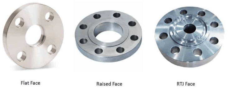
Raised face flange has a small portion around the bore is raised from the face. The gasket seat on this raised face. The height of the raised face depends on the flange pressure-temperature rating that is known as a class of the flange. For 150# & 300# height of the raised face is 1/6” and above 300# it is 1/4”. The inside bore circle type of gasket is used with a raised face flange.
As the name suggests, the flat face flange has a flat face. Flat face flanges are used when the counter-flanges are flat faces. This condition occurs mainly in connection to Cast Iron equipment, valves, and specialties. A full-face gasket is used when a flat face flange is used.
Ring joint type face flange has a specially designed grove in which metal gasket seat. This type of flange is used in high pressure and temperature services.
Flanges and their joints – Circular flanges for pipes, valves, fittings and accessories, PN designated – Part 1: Steel flanges
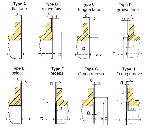
This European standard specifies requirements for circular steel flanges in PN designations PN 2,5 to PN 400 and nominal sizes from DN 10 to DN 4000. This standard specifies the flange types and their facings, dimensions, tolerances, threading, bolt sizes, flange face surface finish, marking, materials, pressure/ temperature ratings and flange masses.
Flange faces have to be smooth enough to ensure a tight, leak-free seal for bolted flanges.
| Type A: flat face | Type D: groove face | Type G: O Ring recess |
|---|---|---|
| Type B: raised face | Type E: spigot | Type H: O Ring groove |
| Type C: tongue face | Type F: recess |
| DN | PN | f1 | f2 | f3 | f4 | w | x | y | z | α | R | |||||||||||
|---|---|---|---|---|---|---|---|---|---|---|---|---|---|---|---|---|---|---|---|---|---|---|
| 2.5 | 6 | 10 | 16 | 25 | 40 | 63 | 100 | 160 | 250 | 320 | 400 | |||||||||||
| d1 | ||||||||||||||||||||||
| 10 | 35 | 35 | 40 | 40 | 40 | 40 | 40 | 40 | 40 | 40 | 40 | 40 | 2 | 4.5 | 4 | 2 | 24 | 34 | 35 | 23 | - | 2.5 |
| 15 | 40 | 40 | 45 | 45 | 45 | 45 | 45 | 45 | 45 | 45 | 45 | 45 | 29 | 39 | 40 | 28 | - | |||||
| 20 | 50 | 50 | 58 | 58 | 58 | 58 | 58 | 58 | 58 | 58 | 58 | 58 | 36 | 50 | 51 | 35 | 41º | |||||
| 25 | 60 | 60 | 68 | 68 | 68 | 68 | 68 | 68 | 68 | 68 | 68 | 68 | 43 | 57 | 58 | 42 | ||||||
| 32 | 70 | 70 | 78 | 78 | 78 | 78 | 78 | 78 | 78 | 78 | 78 | 78 | 51 | 65 | 66 | 50 | ||||||
| 40 | 80 | 80 | 88 | 88 | 88 | 88 | 88 | 88 | 88 | 88 | 88 | 88 | 3 | 61 | 75 | 76 | 60 | |||||
| 50 | 90 | 90 | 102 | 102 | 102 | 102 | 102 | 102 | 102 | 102 | 102 | 102 | 73 | 87 | 88 | 72 | ||||||
| 65 | 110 | 110 | 122 | 122 | 122 | 122 | 122 | 122 | 122 | 122 | 122 | 122 | 95 | 109 | 110 | 94 | ||||||
| 80 | 128 | 128 | 138 | 138 | 138 | 138 | 138 | 138 | 138 | 138 | 138 | 138 | 106 | 120 | 121 | 105 | ||||||
| 100 | 148 | 148 | 158 | 158 | 162 | 162 | 162 | 162 | 162 | 162 | 162 | 162 | 5 | 4.5 | 2.5 | 129 | 149 | 150 | 128 | 32º | 3 | |
| 125 | 178 | 178 | 188 | 188 | 188 | 188 | 188 | 188 | 188 | 188 | 188 | 188 | 155 | 175 | 176 | 154 | ||||||
| 150 | 202 | 202 | 212 | 212 | 218 | 218 | 218 | 218 | 218 | 218 | 218 | 218 | 183 | 203 | 204 | 182 | ||||||
| 200 | 258 | 258 | 268 | 268 | 278 | 285 | 285 | 285 | 285 | 285 | 285 | 285 | 239 | 259 | 260 | 238 | ||||||
| 250 | 312 | 312 | 320 | 320 | 335 | 345 | 345 | 345 | 345 | 345 | 345 | - | 292 | 312 | 313 | 291 | ||||||
| 300 | 365 | 365 | 370 | 378 | 395 | 410 | 410 | 410 | 410 | - | - | - | 4 | 343 | 363 | 364 | 342 | |||||
| 350 | 415 | 415 | 430 | 438 | 450 | 465 | 465 | 465 | - | - | - | - | 5.5 | 5 | 3 | 395 | 421 | 422 | 394 | 27º | 3.5 | |
| 400 | 465 | 465 | 482 | 490 | 505 | 535 | 535 | 535 | - | - | - | - | 447 | 473 | 474 | 446 | ||||||
| 450 | 520 | 520 | 532 | 550 | 555 | 560 | 560 | 560 | - | - | - | - | 497 | 523 | 524 | 496 | ||||||
| 500 | 570 | 570 | 585 | 610 | 615 | 615 | 615 | 615 | - | - | - | - | 349 | 375 | 376 | 548 | ||||||
| 600 | 670 | 670 | 685 | 725 | 720 | 735 | 735 | - | - | - | - | - | 5 | 649 | 675 | 676 | 648 | |||||
| 700 | 775 | 775 | 800 | 795 | 820 | 840 | 840 | - | - | - | - | - | 751 | 777 | 778 | 750 | ||||||
| 800 | 880 | 880 | 905 | 900 | 930 | 960 | 960 | - | - | - | - | - | 856 | 882 | 883 | 855 | ||||||
| 900 | 980 | 980 | 1005 | 1000 | 1030 | 1070 | 1070 | - | - | - | - | - | 961 | 987 | 988 | 960 | ||||||
| 1000 | 1080 | 1080 | 1110 | 115 | 1140 | 1180 | 1180 | - | - | - | - | - | 6.5 | 6 | 4 | 1062 | 1092 | 1094 | 1060 | 28º | 4 | |
| 1200 | 1280 | 1295 | 1330 | 1330 | 1350 | 1380 | 1380 | - | - | - | - | - | 1262 | 1292 | 1294 | 1260 | ||||||
| 1400 | 1480 | 1510 | 1535 | 1530 | 1560 | 1600 | - | - | - | - | - | - | 1462 | 1492 | 1494 | 1460 | ||||||
| 1600 | 1690 | 1710 | 1760 | 1750 | 1780 | 1815 | - | - | - | - | - | - | 1662 | 1692 | 1694 | 1660 | ||||||
| 1800 | 1890 | 1920 | 1960 | 1950 | 1985 | - | - | - | - | - | - | - | 1862 | 1892 | 1894 | 1860 | ||||||
| 2000 | 2090 | 2125 | 2170 | 2150 | - | - | - | - | - | - | - | - | 2062 | 2092 | 2094 | 2060 | ||||||
| 2200 | 2295 | 2335 | 2370 | - | - | - | - | - | - | - | - | - | - | - | - | - | - | - | - | - | - | |
| 2400 | 2495 | 2545 | 2570 | - | - | - | - | - | - | - | - | - | - | - | - | - | - | - | - | - | - | |
| 2600 | 2695 | 2750 | 2780 | - | - | - | - | - | - | - | - | - | - | - | - | - | - | - | - | - | - | |
| 2800 | 2910 | 2960 | 2000 | - | - | - | - | - | - | - | - | - | - | - | - | - | - | - | - | - | ||
| 3000 | 3110 | 3160 | 3210 | - | - | - | - | - | - | - | - | - | - | - | - | - | - | - | - | - | - | |
| 3200 | 3310 | 3370 | - | - | - | - | - | - | - | - | - | - | - | - | - | - | - | - | - | - | - | |
| 3400 | 3510 | 3580 | - | - | - | - | - | - | - | - | - | - | - | - | - | - | - | - | - | - | - | |
| 3600 | 3720 | 3790 | - | - | - | - | - | - | - | - | - | - | - | - | - | - | - | - | - | - | - | |
| 3800 | 3920 | - | - | - | - | - | - | - | - | - | - | - | - | - | - | - | - | - | - | - | - | |
| 4000 | 4120 | - | - | - | - | - | - | - | - | - | - | - | - | - | - | - | - | - | - | - | - | |
Flanges provide the necessary connections to link pipelines. Faces are the mating surface of a flange.
| The type of flange | The type of sealing face | Pressure Class(PN,MPA) |
|---|---|---|
| Plate flange(PL) | Raise Face(RF) | 0.25-2.5 |
| Flat Face( FF) | 0.25-1.6 | |
| Slip on flange(SO) | Raise Face(RF) | 0.6-4.0 |
| Flat Face( FF) | 0.6-1.6 | |
| male and female face (MFM) | 1.0-4.0 | |
| Tongue and groove face (TG) | 1.0-4.0 | |
| Welding Neck Flange(WN) | Raise Face(RF) | 1.0-25.0 |
| male and female face (MFM) | 1.0-16.0 | |
| Tongue and groove face (TG) | 1.0-16.0 | |
| Ring Joint Face(RTJ) | 6.3-25.0 | |
| Flat Face( FF) | 1.0-1.6 | |
| Integral type flange(IF) | Raise Face(RF) | 0.6-25.0 |
| male and female face (MFM) | 1.0-16.0 | |
| Tongue and groove face (TG) | 1.0-16.0 | |
| Ring Joint Face(RTJ) | 6.3-25.0 | |
| Flat Face( FF) | 0.6-1.6 | |
| Socket Weld Flange(SW) | Raise Face(RF) | 1.0-10.0 |
| male and female face (MFM) | 1.0-10.0 | |
| Tongue and groove face (TG) | 1.0-10.0 | |
| Thread Flange(Th) | Raise Face(RF) | 0.6-4.0 |
| Flat Face( FF) | 0.6-1.6 | |
| Lap joint Flange(LP) | Raise Face(RF) | 0.6-1.6 |
| male and female face (MFM) | 1.0-1.6 | |
| Tongue and groove face (TG) | 1.0-1.6 | |
| Blind flange(BL) | Raise Face(RF) | 0.25-25.0 |
| male and female face (MFM) | 1.0-16.0 | |
| Tongue and groove face (TG) | 1.0-16.0 | |
| Ring Joint Face(RTJ) | 6.3-25.0 | |
| Flat Face( FF) | 0.25-1.6 |
Flanges are welded to pipe and equipment nozzle. Accordingly, it is manufactured from the following materials;
The list of materials used in manufacturing is covered in ASME B16.5 & B16.47.
Commonly used Forged material grads are
| Material | Fittings | Flanges | Valves | Bolts & Nuts |
|---|---|---|---|---|
| Carbon Steel | A234 Gr WPA | A105 | A216 Gr WCB | A193 Gr B7 A194 Gr 2H |
| A234 Gr WPB | A105 | A216 Gr WCB | ||
| A234 Gr WPC | A105 | A216 Gr WCB | ||
| Carbon Steel Alloy High-Temp | A234 Gr WP1 | A182 Gr F1 | A217 Gr WC1 | A193 Gr B7 A194 Gr 2H |
| A234 Gr WP11 | A182 Gr F11 | A217 Gr WC6 | ||
| A234 Gr WP12 | A182 Gr F12 | A217 Gr WC6 | ||
| A234 Gr WP22 | A182 Gr F22 | A217 Gr WC9 | ||
| A234 Gr WP5 | A182 Gr F5 | A217 Gr C5 | ||
| A234 Gr WP9 | A182 Gr F9 | A217 Gr C12 | ||
| Carbon Steel Alloy Low-Temp | A420 Gr WPL6 | A350 Gr LF2 | A352 Gr LCB | A320 Gr L7 A194 Gr 7 |
| A420 Gr WPL3 | A350 Gr LF3 | A352 Gr LC3 | ||
| Austenitic Stainless Steel | A403 Gr WP304 | A182 Gr F304 | A182 Gr F304 | A193 Gr B8 A194 Gr 8 |
| A403 Gr WP316 | A182 Gr F316 | A182 Gr F316 | ||
| A403 Gr WP321 | A182 Gr F321 | A182 Gr F321 | ||
| A403 Gr WP347 | A182 Gr F347 | A182 Gr F347 |
The usual materials of flanges include stainless steel, carbon steel, aluminum and plastic. The choice of the material largely depends on the purpose of the flange. For example, stainless steel is more durable and is necessary for heavy use. On the other hand, plastic is more feasible for use in the home because of its reasonable price and easy installation. The materials used for flanges are under the designation of the American Society of Mechanical Engineers.
The most common materials for pipe flanges (forged grades) are: ASTM A105 (carbon steel high temperature to match A53/A106/API 5L pipes), A350 Grades LF1/2/3 (carbon steel low temperature to match A333 pipes), A694 Grades F42 to F80 (high yield carbon steel to match API 5L pipe grades), ASTM A182 Grades F5 to F91 (alloy steel flanges to match A335 pipes), A182 Grade F304/316 (stainless steel flanges to match A312 SS pipes), A182 Gr. F44/F51/F53/F55 (duplex and super duplex to match A790/A928 pipes) and various nickel alloy grades (Inconel, Incoloy, Hastelloy, Monel).
The material qualities for these flanges are defined in the ASTM standards.
What are ASTM Grades?
For example, a carbon steel pipe can be identified with Grade A or B, a stainless-steel pipe with Grade TP304 or Grade TP321, a carbon steel fitting with Grade WPB etc.
| Steel No. | Type | C | Si | S | P | Mn | Cr | Ni | Mo | Other | ób | ós | δ5 |
|---|---|---|---|---|---|---|---|---|---|---|---|---|---|
| WP304 | 0.08 | 1 | 0.03 | 0.045 | 2 | 18-20 | 8-11 | 515 | 205 | 28 | |||
| WP304H | 0.04-0.1 | 1 | 0.03 | 0.045 | 2 | 18-20 | 8-11 | 515 | 205 | 28 | |||
| WP304L | 0.035 | 1 | 0.03 | 0.045 | 2 | 18-20 | 8-13 | 485 | 170 | 28 | |||
| WP304LN | 0.03 | 0.75 | 0.03 | 0.045 | 2 | 18-20 | 8-10.5 | N2:0.1-0.16 | 515 | 205 | 28 | ||
| WP304N | 0.08 | 0.75 | 0.03 | 0.045 | 2 | 18-20 | 8-11 | N2:0.1-0.16 | 550 | 240 | 28 | ||
| WP309 | 0.15 | 1 | 0.03 | 0.045 | 2 | 22-24 | 12-15 | 515 | 205 | 28 | |||
| WP310 | 0.15 | 1.5 | 0.03 | 0.045 | 2 | 24-26 | 19-22 | 515 | 205 | 28 | |||
| WP316 | 0.08 | 1 | 0.03 | 0.045 | 2 | 16-18 | 10-14 | 2-3 | 515 | 205 | 28 | ||
| WP316H | 0.04-0.1 | 1 | 0.03 | 0.045 | 2 | 16-18 | 10-14 | 2-3 | 515 | 205 | 28 | ||
| WP316LN | 0.03 | 0.75 | 0.03 | 0.045 | 2 | 16-18 | 11-14 | 2-3 | N2:0.1-0.16 | 515 | 205 | 28 | |
| WP316L | 0.035 | 1 | 0.03 | 0.045 | 2 | 16-18 | 10-16 | 2-3 | 485 | 170 | 28 | ||
| WP316N | 0.08 | 0.75 | 0.03 | 0.045 | 2 | 16-18 | 11-14 | 2-3 | N2:0.1-0.16 | 550 | 240 | 28 | |
| WP317 | 0.08 | 1 | 0.03 | 0.045 | 2 | 18-20 | 11-15 | 3-4 | 515 | 205 | 28 | ||
| WP317L | 0.03 | 1 | 0.03 | 0.045 | 2 | 18-20 | 11-15 | 3-4 | 515 | 205 | 28 | ||
| WP321 | 0.08 | 1 | 0.03 | 0.045 | 2 | 17-20 | 9-13 | Ti:5C-0.7 | 515 | 205 | 28 | ||
| WP321H | 0.04-0.1 | 1 | 0.03 | 0.045 | 2 | 17-20 | 9-13 | Ti:4C-0.7 | 515 | 205 | 28 | ||
| WP347 | 0.08 | 1 | 0.03 | 0.045 | 2 | 17-20 | 9-13 | Nb+Ta:10C-1.1 | 515 | 205 | 28 | ||
| WP347H | 0.04-0.1 | 1 | 0.03 | 0.045 | 2 | 17-20 | 9-13 | Nb+Ta:8C-1 | 515 | 205 | 28 | ||
| WP348 | 0.08 | 1 | 0.03 | 0.045 | 2 | 17-20 | 9-13 | Ta:0.1 | 515 | 205 | 28 | ||
| WP348H | 0.04-0.1 | 1 | 0.03 | 0.045 | 2 | 17-20 | 9-13 | Ta:0.1 | 515 | 205 | 28 |
| Grade | UNS | Tensile Strength, min | Yield Strength,min | Elongation min % in 4D | |||
|---|---|---|---|---|---|---|---|
| ksi | MPa | ksi | MPa | Longit % | Trans% | ||
| ALL | ALL | 75 | 515 | 30 | 205 | 28 | 20 |
| 304L | S30403 | 70 | 485 | 25 | 170 | 28 | 20 |
| 316L | S31603 | 70 | 485 | 25 | 170 | 28 | 20 |
| 304N | S30451 | 80 | 550 | 35 | 240 | 28 | 20 |
| 316N | S31651 | 80 | 550 | 35 | 240 | 28 | 20 |
| S31726 | 80 | 550 | 35 | 240 | 28 | 20 | |
| XM-19 | S20910 | 100 | 690 | 55 | 380 | 28 | 20 |
| S31254 | 94-119 | 650-820 | 44 | 300 | 28 | 20 | |
| S34565 | 115 | 795 | 60 | 415 | 28 | 20 | |
| S33228 | 73 | 500 | 27 | 185 | 28 | 20 | |
The most frequently asked questions regarding flanges and flange fittings have to do with how flanges fit on specific steel tube and steel pipe ends.
Flanges have flat or flush surfaces that are vertical to the pipe to which they are attached. The attachment process involves mechanically joining two or more faces using bolts, adhesives, collars, or welds. Due to the attachment requirements, a flange must fit the equipment or pipe that it’s designed. That’s why it’s necessary to check all the possible specifications and dimensions to ascertain that it’s of the right size, type, and material.
Pipe flanges, gaskets, and bolts are the three parts that comprise a flanged connection. Gaskets and bolts are typically made of the same flange materials or a material approved for the pipe components. Each component comes in various materials that suit specific applications and must be matched correctly for proper functioning. The gaskets come in two conventional types: full-face gaskets and ring gaskets. Full-face gaskets have the bolt holes visible and pair up with raised-face gaskets. Ring gaskets tend to be smaller rings minus the bolt holes and pair up with flat-faced flanges. Securing the flange components requires matching the surfaces evenly and plumb, adjusting as needed for a uniform fit. Once all surfaces match, bring the flanges together and secure at least two of the bolts. Refine the alignment, so the remaining bolt holes match and their corresponding bolts are tightly secured.
Properly sizing a flange for pipe use depends not only on the type of flange but its compatible piping. The pipe must slip into the flange’s inside diameter easily and securely, and the outside diameter should cover wall holes. Once you determine the specific flange type and material you need for the job, you’ll need to take several measurements. The four measurements you’ll need are the inside diameter, outside diameter, bolt hole count, and bolt hole center. You’ll need to align each of these measurements from opposing bolt holes to get the most accurate readings. Take all measurements from edge to edge and try to get as precise as possible to match the correct product. Round up bolt diameter to the next half or whole step since bolts measure half or whole inches. Once you have all four measurements, check them against the manufacturer’s table to find the correct flange. Most manufacturers list these specifications on their websites for easy reference.
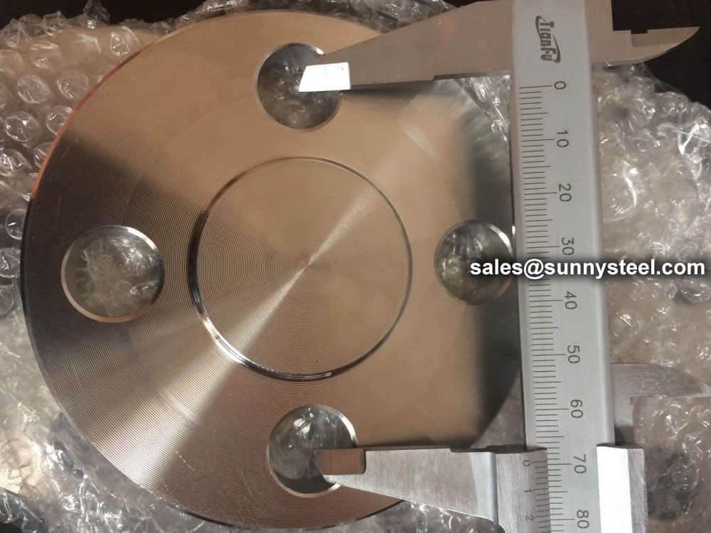
Before dispatching from manufacture each flange is inspected to ensure quality. During an inspection you have to check the following;
ASME B16.5 and B16.47 standards cover permissible tolerances for inspection.
When a piping joint requires to be dismantled, flanges are being used. These are primarily used on equipment, valves, and specialty items. Breakout flanges are provided at predetermined intervals in certain pipelines where maintenance is a regular occurrence. The flanges, gaskets, and bolting make up a flanged joint, which is made up of three separate but interconnected components. To achieve a leak-proof joint, special controls are required in the selection and application of all of these elements.
Here are the details of Flanges about their advantages and their applications.
Pipes, valves, pumps, and other parts are connected with flanges to form a piping system. Generally, flanges are welded or screwed together. The use of flanges makes pipe system maintenance and repair a breeze. Instead of taking the entire pipe for inspection, a small section of the pipe can be carefully investigated to use a flange to locate the fault.
The following are the five most important benefits of The following are the five most important benefits of flanges:
A flange is a method of connecting pipes, valves, pumps, and other equipment to form a piping system. It also provides easy access for cleaning, inspection, or modification. Flanges are usually welded or screwed.
In many applications, engineers need to find a way to close off a chamber or cylinder in a very secure fashion, usually because the substance inside must differ from the substance outside in composition or pressure.
They do this by fastening two pieces of metal or other material together with a circle of bolts on a lip. This “lip” is a flange.
Plumbing
You can connect two sections of metal piping by soldering or welding them together, but pipes connected in this way are very susceptible to bursting at high pressures. A way of connecting two sections of pipe more securely is by having flanged ends that you can connect with bolts. This way, even if gases or liquids build up to high pressures inside the pipe, it will often hold with no problem.
Mechanics
In order to connect two sections of a large, enclosed area, it is often best to used flanges and bolts. An example of this is the connection between the engine and the transmission in an automobile. In this case, both the engine and the transmission contain a number of moving parts that can easily get damaged if they get dust or other small objects inside of them. By connecting the outer casings of the engine and transmission in this way, engineers protect the inner workings of both.
Electronics
Flanges have a specific purpose in cameras and other electronic devices. Though flanges in such items do not usually have to sustain high pressures, they do have to hold tight so they can keep out harmful particles. These flanges are usually found connecting two different materials, such as the glass of a lens and the rest of the body of the camera.
There are many ways to connect flanges, including threading, welding or bolting. The threaded flange is best for low pressure or smaller pipelines because it can maintain its seal. When your pipeline is larger or high pressure, then the welded flange is preferable. A boiler room is one place where welded blind flanges might be used, due to the high pressure involved.
A flange is a external rib at the end of pipes, valves and other flow devices to assemble them.
Dimensions of the flanges are up to specific Standards : DIN, ANSI, AS, BS, JIS
A flanged connection requires two flanges (the “main” and the “companion”), a set of bolts and nuts (whose number depends on the flange diameter and class) and two sealing gaskets. Flanged connections have to be executed and supervised by trained personnel, as the quality of the joint has a critical impact on the performance of the piping system / pipeline (the standard TSE – TS EN 1591 Part 1-4, “Flanges and their joints”, defines a number of requirements for the execution of proper flanged connections). Whereas all elements of the joint are critical, experience shows most leaks are originated by the improper installation of the sealing elements, i.e. the gaskets.
The typical pipe to flange connections are welded or threaded. Welded flanges are used for pipelines and piping systems with high pressures and temperatures, and with diameters above 2 inches.
Threaded connections are instead used for installations of smaller diameter and not subject to severe mechanical forces such as expansion, vibration, contraction, oscillation (forces that would crack the threaded joint). In all these critical cases, butt weld connections are recommended.
Steel flanges must be packed with seaworthy packing method then delivery to customers, usually the packing way include wooden box, wooden pallet, iron & steel cage, iron & steel pallet etc.
Before dispatching from manufacture each flange is inspected to ensure quality. During an inspection you have to check the following;
 |
 |
 |
ASME B16.5 and B16.47 standards cover permissible tolerances for inspection.
Shipping mark stick to outside of package. Following shall be marked on flange body 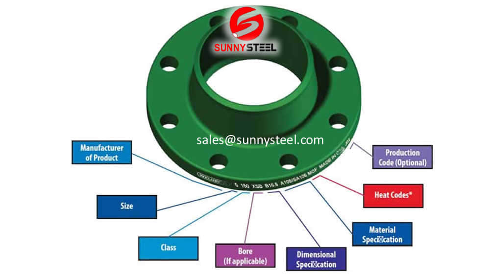
Packing Because of the normal wooden boxes or wooden pallets have to do fumigation treatment, we usually use plywood pallet or plywood case or box to pack steel flanges without fumigation treatment. 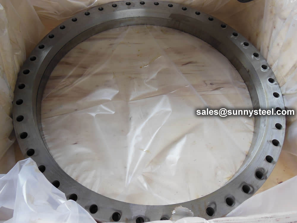
Need to inquire about our products? Fill out the form below and our staff will be in touch!
Q: How long is your delivery time?
A: The delivery time of customized products is generally 25 35 days, and non customized products are generally shipped within 24 hours after payment.
Q: Do you provide samples? Is it free?
A: If the value of the sample is low, we will provide it for free, but the freight needs to be paid by the customer. But for some high value samples, we need to charge a fee.
Q: What are your payment terms?
A: T/T 30% as the deposit,The balance payment is paid in full before shipment
Q: What is the packaging and transportation form?
A: Non steaming wooden box and iron frame packaging. Special packaging is available according to customer needs. The transportation is mainly by sea.
Q: What is your minimum order quantity?
A: There is no minimum order quantity requirement. Customized products are tailor made according to the drawings provided by the customer.


